Method for operating a wind turbine based on degradation of wind turbine blade

a technology of wind turbine blades and operations, which is applied in the direction of machines/engines, mechanical equipment, proportional integration algorithms, etc., can solve the problems of aerodynamically shaped outer surfaces, ice accumulation on the leading edge, and sand particles and other wind-born debris erode the critical leading edge of the fast moving wind turbine blades, so as to achieve maximum power production, reduce generator torque, and increase rotation speed

Active Publication Date: 2019-01-22
YUANJIAN WIND POWER JIANGYINENVISION ENERGY CO LTD
View PDF27 Cites 5 Cited by
  • Summary
  • Abstract
  • Description
  • Claims
  • Application Information

AI Technical Summary

Benefits of technology

[0014]An object of the invention is to provide a wind turbine that allows the aerodynamics degradation of the wind turbine blades to be monitored.
[0073]As described above, the estimator module further comprises a comparator used to determine the deviation or error between the predicted set of measurements and the current set of measurements. This deviation or error is used by a corrector to correct the next predicted set of measurements. The estimator module, e.g., the corrector, is configured to calculate the gain used to correct the next predicted set of measurements. The gain is fed back to the first model and / or the second model and used to calculate the next set of measurements and / or the next state of the system. This increases the accuracy of the predicted set of measurements.

Problems solved by technology

It is known that rain, sand, dust, and other wind-born debris gradually chip and erode the critical leading edge of the fast moving wind turbine blades.
Also, salt, pollution and sticky dust particles will accumulate on the outer surface adding weight and roughness to the wind turbine blade, thereby altering the aerodynamically shaped outer surfaces until rain or a maintenance wash cleans them off.
Furthermore, ice can accumulate on the leading edges if the air contains droplets of super-cooled water, and lightning strikes may form cracks anywhere along the wind turbine blade despite that the wind turbine blade is outfitted with electrically conductive elements.
Any of these conditions may degrade the carefully designed aerodynamic profile of the wind turbine blade, therefore the wind turbine blade need to be cleaned and repaired to maintain the aerodynamic performance.
Since the damage and aerodynamic degradation are primarily concentrated at the leading edges, special materials have to be applied to repair and protect the leading edges of the wind turbine blades, however servicing the blades is dangerous work as the tower is typically 90 meters high and subjected to wind gusts.
Blade repair and other maintenance works are only occasionally performed as this work is expensive and adds to the downtime of the wind turbine.
The control systems of such wind turbines are typically tuned according to nominal aerodynamic specifications, where deviations from these nominal specifications cause the control system to de-tune and reduce the power production.
However, the wind turbine is not operated optimally prior to the degradation and is not able to compensate for the progressive change of the aerodynamics occurring beyond these partially degraded specifications.
However, the teachings do not hint how the control system is re-tuned or how this control parameter should be adjusted.
However, such an anemometer mounted on the wind turbine does not measure the actual wind speed, but the downstream wind speed after it has been significantly affected by the rotor.
Large wind turbines have a rotor covering a great area, e.g., 7854 square meters [m2] for a rotor with rotor blades of 50 meters, thus the wind speed measured at a single anemometer position does not provide representative value of the wind speed impacting the entire rotor.
This control method is not designed to monitor the extent of the aerodynamic degradation of the wind turbine blades, nor is it provides an effective control method for compensating for the changing aerodynamic properties of the wind turbine blades.

Method used


Image

  • Method for operating a wind turbine based on degradation of wind turbine blade
  • Method for operating a wind turbine based on degradation of wind turbine blade
  • Method for operating a wind turbine based on degradation of wind turbine blade

Examples


first embodiment

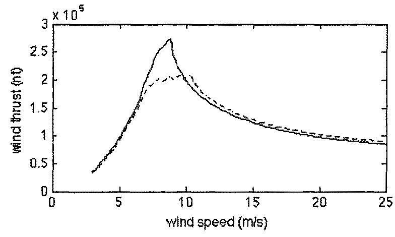
[0122]FIG. 6 shows the adapted pitch angle, generator torque, and rotation speed of the wind turbine optimized for maximum power production according to a In this embodiment, the ideal aerodynamic thrust and the ideal aerodynamic torque of the normal wind turbine of FIG. 3 is scaled by means of a common scaling factor, kc, according to equation (1). Here the ideal aerodynamic thrust and torque coefficients are scaled by means of a factor of kc=0.8, after which the control system adapts the ideal pitch angle, generator torque, and rotation speed according to these scaled aerodynamic coefficients.

second embodiment

[0123]FIG. 7 shows the adapted pitch angle, generator torque, and rotation speed of the wind turbine optimized for maximum power production according to a In this embodiment, the rotor radius is scaled by means of a scaling factor, kR, to determine a virtual rotor radius which in turn is used to scale the ideal aerodynamic thrust and the ideal aerodynamic torque of the normal wind turbine of FIG. 3 according to equation (2). Here the ideal aerodynamic thrust and torque coefficients are scaled by means of a factor of kR=0.92, after which the control system adapts the ideal pitch angle, generator torque, and rotation speed according to these scaled aerodynamic coefficients.

[0124]As illustrated in the graphs of FIGS. 6 and 7, these adapted values (solid lines) provide a more accurate representation of those (dotted lines) of the degraded wind turbine of FIG. 3. This allows the degraded wind turbine to increase the thrust acting on the rotor and thus maximize the power production durin...

third embodiment

[0130]FIG. 12 shows the adapted pitch angle, generator torque, and rotation speed of the wind turbine optimized for maximum power production according to a In this embodiment, a scaling factor, ka, is determined based on the ratio shown in FIG. 11 according to one or more criteria. The ideal induction factor of the normal wind turbine of FIG. 3 is scaled by means of this scaling factor which in turn is used to scale the aerodynamic coefficients.

[0131]The ideal aerodynamic torque coefficient of the normal wind turbine of FIG. 3 is scaled according to equation (4) using the induction factor of FIG. 9 and this scaling factor, ka. Here the ideal aerodynamic torque coefficient is scaled by means of a factor of ka=0.72.

[0132]As illustrated in FIG. 12, these adapted values (solid lines) provide a more accurate representation of those (dotted lines) of the degraded wind turbine of FIG. 3. Furthermore, scaling the ideal aerodynamic coefficients using equation (3) means that the actual aerod...


PUM


Abstract

A control method and a wind turbine for adaptively adjusting the operation of the wind turbine to maintain maximum power production during degraded conditions. The control system has an estimator module that determines a scaling factor based on the current set of control signals and at least the current set of measurement of the operating parameters. The scaling factor is transmitted to a control module which scales at least one aerodynamic property of the rotor based on this scaling factor. The control module further determines the ideal settings for the control signals based on the scaled aerodynamic properties. The present control method scales the aerodynamic properties to provide a better representation of the actual degraded aerodynamic properties.

Description

BACKGROUND OF THE INVENTION[0001]Field of the Invention[0002]The present invention relates to an operation method and a wind turbine configured to determine aerodynamic changes in the wind turbine blades due to ageing and degradation by environmental conditions, and to adapt the control method based on these changes.[0003]Description of Related Art[0004]It is known that rain, sand, dust, and other wind-born debris gradually chip and erode the critical leading edge of the fast moving wind turbine blades. Also, salt, pollution and sticky dust particles will accumulate on the outer surface adding weight and roughness to the wind turbine blade, thereby altering the aerodynamically shaped outer surfaces until rain or a maintenance wash cleans them off. Furthermore, ice can accumulate on the leading edges if the air contains droplets of super-cooled water, and lightning strikes may form cracks anywhere along the wind turbine blade despite that the wind turbine blade is outfitted with elec...

Claims


Application Information

Patent Timeline
Patent Type & Authority Patents(United States)
IPC IPC(8): F03D7/04F03D7/02F03D17/00F03D9/00F03D9/25F03D80/40
CPCF03D7/044F03D7/0224F03D7/046F03D9/25F03D17/00Y02E10/723F03D80/40F05B2270/20F05B2270/336F03D7/043F05B2270/1033F05B2270/30F05B2270/602F05B2270/705Y02E10/72
Inventor WILSON, KITCHENER CLARKZHANG, FENGCHEN, LINSUN, YUPING
Owner YUANJIAN WIND POWER JIANGYINENVISION ENERGY CO LTD
Why Eureka
Try Eureka