
Micromachined pressure sensor and method of making the same

a micro-machined silicon and pressure sensor technology, applied in the direction of fluid pressure measurement by thermal means, measurement devices, instruments, etc., can solve the problems of small dynamic range or low span sensitivities, inability to meet the needs of measurement precision, etc., to achieve high accuracy and high precision pressure data, large dynamic range and large dynamic rang

Active Publication Date: 2019-02-19
WISENSTECH
View PDF6 Cites 2 Cited by
  • Summary
  • Abstract
  • Description
  • Claims
  • Application Information

AI Technical Summary

Benefits of technology

[0010]It is therefore desired to provide the design and manufacture process for a pressure sensor that shall be able to achieve high accurate pressure data in a large dynamic range without being interfered by any medium movement while performing the measurement. The said pressure sensor shall further be able to measure absolute pressure, gauge pressure and differential pressure. The said pressure sensor shall have the capability to operate in the presence of a particle or contaminants and therefore it shall be able to be package in various formalities with or without the nozzle or pressure port structure. It shall also be able to have large dynamic range and high sensitivity at low pressure measurement ends, and desirably in a linearity output. Such said pressure sensor shall also be easily manufactured with a process compatible with other sensing devices and shall be easily integrated with other sensing devices such as a flow sensor in a miniaturized footprint. It shall also be manufactured at a low cost such that it can be applied for a vast spectrum of applications.

Problems solved by technology

While these technologies are very mature and become cost effective, the pressure sensors made of such do have undesired performances and not cost effective in order to have high precision.
Because of the size of the piezo resistors on a membrane of the diaphragm, the local stress changes or deflections in membrane are rather small leading to a small dynamic range or low span sensitivities and large error towards the low end of detection (usually specified as the full scale errors).
In addition to the large offset errors, the hysteresis and drift also limit the capability of this technology in measurement precision.
However, in order to achieve a good sensitivity the membrane size needs to be increased and the membrane thickness shall be reduced which not only lead to large device size but in return it is resulted in a significantly reduced burst pressure, increased nonlinearity in output and reduced dynamic range.
Both of the piezo resistive and capacitive pressure sensors suffers the nonlinearity in their full span measurement data acquisition which intrinsically make them difficult to achieve the desired full span accuracy.
Therefore this approach although used a thermal approach to measure the absolute gas pressure, the achievable accuracy as well as the signal process complicated the device making.
In addition, this sensor cannot be applied to measure the gauge pressure or differential pressure as the thermal parameters are acquired from the suspended cavity with openings to the gas medium to be measured.
Because of the limitation of the channel dimensions, such a device could mostly applied for small differential pressure measurement and in many applications it is used for measurement of flow rate in a bypass formality and cannot be applied for measurement of differential pressures without flow pass-through even though it is named as a differential pressure sensor.
As the interface shall be critical to the data acquired which makes the fabrication very difficult and any unknown materials at the interface will alter the results.
While the disclosure did not indicate the chamber gap size, the proposed metal diaphragm shall not have the capability for sensing low pressures, and in particular, the thermistors placed on silicon nitride and silicon substrate combined shall make the thermistor sensing capability being nullified as the thermal conductivities of the silicon nitride and silicon combined is far larger than any trivial changes inside the proposed chamber, as it is obvious that the tiny compress of the gas inside the chamber shall not provide meaningful changes in its gas thermal (temperature) properties.
In many of the current applications, the pressure sensors are packaged into a nozzle formality to avoid any disturbance from the medium flow interference to the pressure measurement, which makes the integration of a flow and a pressure sensor even difficult.
The nozzle package also limited the possibility of integration into a miniaturized formality with other sensing elements.
As the nozzle has a very small passage to the pressure sensing element, any contaminant blockage shall lead to the completely loss of the functionality of the pressure sensors.

Method used


Image

  • Micromachined pressure sensor and method of making the same
  • Micromachined pressure sensor and method of making the same
  • Micromachined pressure sensor and method of making the same

Examples


Embodiment Construction

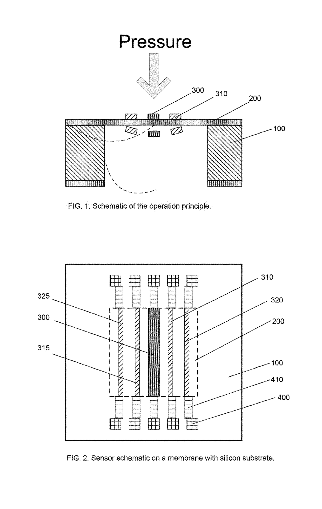
[0038]The preferred operation principle of the said micromachined pressure sensor is showed in FIG. 1. The pressure sensor is made of a micromachined diaphragm structure on a silicon substrate. The pressure sensing is based on the external pressure induced membrane mechanical defection of the diaphragm structure. A micro-heater on the said membrane creates a stable thermal field and at least one pair of the thermistors symmetrically or asymmetrically placed at the both side against the micro-heater. When an external pressure is applied to the one side of the said membrane, the membrane shall be deflected due to the mechanical force which shall result in a change in the thermal field due to the position changes of the thermistors, and the thermistors shall register such changes which are further correlated to the applied pressures. This sensing scheme is therefore referred as a thermal field pressure sensor (TFPS). Compared to the current most commonly applied pressure sensing techno...


PUM

PropertyMeasurementUnit
thicknessaaaaaaaaaa
thicknessaaaaaaaaaa
thicknessaaaaaaaaaa

Abstract

The design and manufacture method of a pressure sensor utilizing thermal field sensing with a thermal isolated membrane of a diaphragm structure is disclosed in the present invention. This device is made with silicon micromachining (a.k.a. MEMS, Micro Electro Mechanical Systems) process for applications of pressure measurement with large dynamic range, high accuracy and high stability during temperature variation. This device is applicable for all types of pressure metrology. The said thermal field pressure sensing device operates with thermistors on a membrane of the diaphragm structure made of silicon nitride with a heat isolation cavity underneath or a single side thermal isolated silicon nitride membrane with a reference cavity. This device can be seamlessly integrated with a thermal flow sensor with the same process.

Description

BACKGROUND OF THE INVENTION1. Field of the Invention[0001]This invention relates to micromachined silicon sensors or Micro Electro Mechanical Systems (MEMS) pressure sensing technology that measures the absolute or relative pressures in a gaseous or liquid media. The present invention also relates to thermal properties of a diaphragm based sensors. This invention additionally provides the design and make of a micromachined pressure sensor using thermal sensing principle. The present invention specifically relates design and process of making the same for a pressure sensor having compatible process flow with those for a thermal flow sensor with a diaphragm.2. Description of the Related Art[0002]Pressure sensor is one of the most commonly used sensing devices in multiple disciplines. There are quite a few sensing technologies that have been employed for making of the pressure sensing devices, such as piezo resistive (e.g., Izadnegahdar, A. et al, Method of manufacturing a thin piezo r...

Claims


Application Information

Patent Timeline
Patent Type & Authority Patents(United States)
IPC IPC(8): G01L9/00
CPCG01L9/0054G01L9/0051G01L9/0041G01L11/002
Inventor HUANG, LIJICHEN, CHIH-CHANG
Owner WISENSTECH
Learn More