Sampling and preparation system and its implementation method

a technology of sampling and preparation system, applied in the direction of lighting and heating apparatus, instruments, separation processes, etc., can solve the problems of huge damage to the environment, sharp increase of electric power demand, sharp decrease of coal storage, etc., and achieve the effect of low cost, accurate test, and simple structur

Active Publication Date: 2019-02-26
ZHEJIANG UNIV
View PDF4 Cites 6 Cited by
  • Summary
  • Abstract
  • Description
  • Claims
  • Application Information

AI Technical Summary

Benefits of technology

[0060]By setting a pressure-bearing shell outside the sample bin, the carbon dioxide in the cavity of the sample bin may be kept in a relatively stable phase state, so that the carbon dioxide may be fully mixed with the scintillator. By setting the cavity which diffuses reflection, the high-energy electrons decay from the 14C in the carbon dioxide may collide with scintillator monomer, so that the scintillator monomer is in the excited state. When the scintillator monomer is de-excitation, a photon with a wavelength of about 380 nm will be generated. These photons may enter

Problems solved by technology

With the social development and economic improvement, there is a sharp increase of demand of electric power, and a sharp decrease of coal storage, and also huge damage to our environment.
However, the coal's 14C radioactivity decays mostly, because of being buried deep in the ground for millions of years.
While the biomass blending rate is low, accelerator mass spectrometry (AMS) is the most accurate de

Method used


Image

  • Sampling and preparation system and its implementation method
  • Sampling and preparation system and its implementation method
  • Sampling and preparation system and its implementation method

Examples


first embodiment

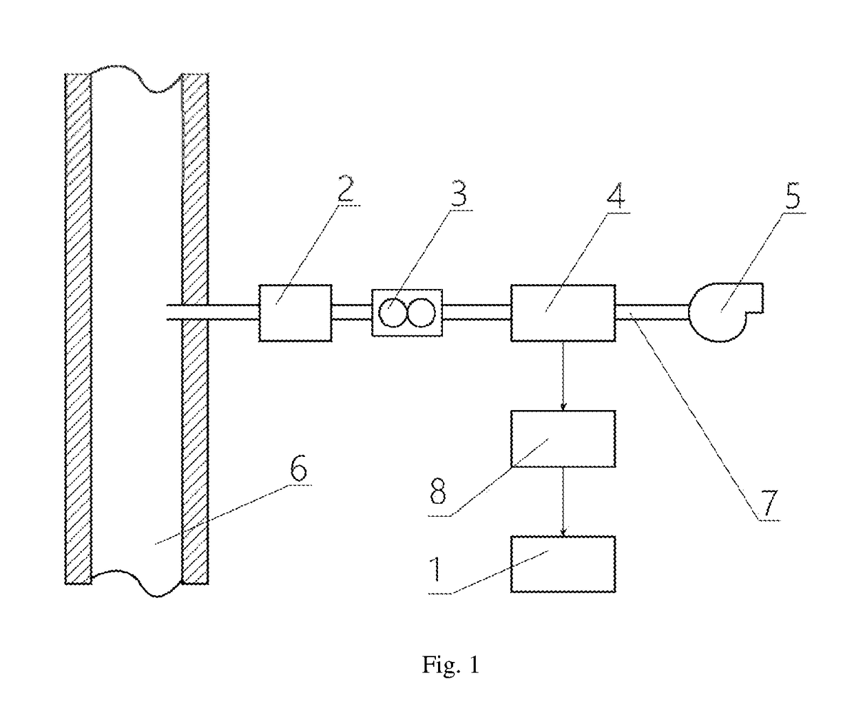
[0089]The first embodiment provides a sampling and preparation system, set in a coal and biomass co-fired power station, as shown in the FIG. 1, including:

[0090]The sampling pipe 7 connected with the boiler flue 6 of the co-fired power station, and the sampling pipe 7 from the end close to the boiler flue 6 to the end away from boiler flue 6 are sequentially arranged as: the filtering device 2, the mass flow controller 3, the carbon dioxide trap 4 and the pumping device 5.

[0091]The sampling and preparation system also includes the carbon dioxide transferring device 8 and the 14C testing device 1. The carbon dioxide transferring device 8 is used to transferring the carbon dioxide from the carbon dioxide traps 4 into the 14C testing device 1, and the 14C testing device 1 is used for measuring the 14C in the carbon dioxide.

[0092]The arrow in the FIG. 1 presents the transferring direction of the carbon dioxide.

[0093]The carbon dioxide trap 4 in the present embodiment may be a cryogenic ...

second embodiment

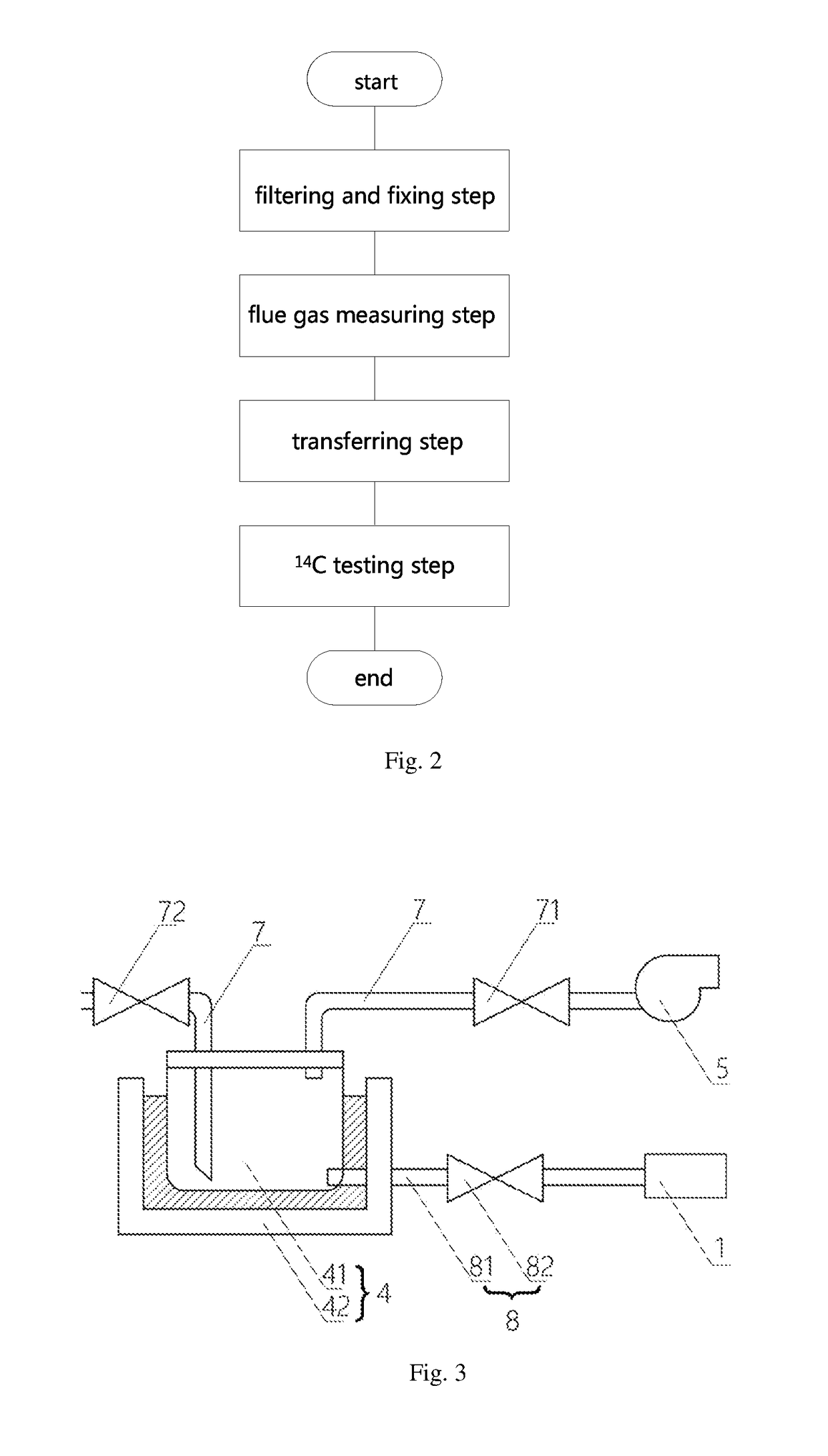
[0106]The second embodiment provides a sampling and preparation system, which is improves the sampling and preparation system in the first embodiment. The main improvement is that, in the second embodiment, as shown in the FIG. 3, the carbon dioxide trap includes:

[0107]the capturing vessel 41 for fixing the carbon dioxide, and the temperature adjusting device 42 for adjusting the temperature of the capturing vessel 41.

[0108]The evacuation valve 71 is positioned on the sampling pipe 7, between the pumping device 5 and the carbon dioxide trap 4. And the preposition valve 72 is positioned on the sampling pipe 7, between the mass flow controller 3 and the carbon dioxide trap 4.

[0109]The transferring device includes the transferring pipeline 81, one end of the transferring pipeline 81 is connected with the carbon dioxide trap 4 and the other end of the transferring pipeline 81 is connected with the 14C testing device 1.

[0110]The first transferring valve 82 is positioned on the transferri...

third embodiment

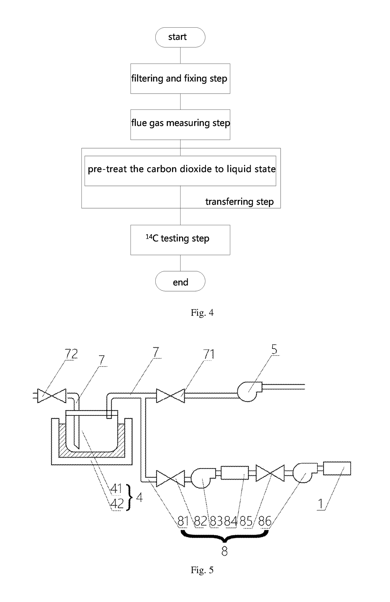
[0122]The third embodiment provides a sampling and preparation system, which further improves the sampling and preparation system in the second embodiment. The main improvement is that, in the third embodiment, as shown in the FIG. 5, the transferring pipeline 81 from the end close to the carbon dioxide trap 4 to the end away from the carbon dioxide trap 4 are sequentially arranged as:

[0123]the gas compressor 83, the pressuring vessel 84, the second transferring valve 85 and the transferring pump 86.

[0124]The first transferring valve 82 is positioned between the gas compressor 83 and the carbon dioxide trap 4.

[0125]The gas compressor 83 is used to compress the carbon dioxide to liquid or supercritical state in the pressuring vessel 84.

[0126]The transferring pump 86 is used to transfer the carbon dioxide from the pressuring vessel 84 into the 14C testing device 1.

[0127]The present embodiment also provides a sampling and preparation method, which is different from the second embodimen...


PUM


Abstract

A sampling and preparation system is positioned in a coal and biomass co-fired power station, which includes a sampling pipe connected with a boiler flue of the co-fired power station. The sampling pipe from the end close to the boiler flue to the other end away from the boiler flue includes a filtering device, a mass flow controller, a carbon dioxide trap and a pumping device. The sampling and preparation system also includes a carbon dioxide transfer device and a 14C testing device. The carbon dioxide transfer device is applied to transferring the carbon dioxide from the carbon dioxide trap to the 14C testing device which is applied to measuring the 14C in the carbon dioxide sample. The system may calculate the biomass blending ratio of the coal and biomass co-fired power station rapidly.

Description

CROSS-REFERENCE TO RELATED APPLICATIONS[0001]The present application is based on, and claims priority from, Chinese Patent Application No. 201711154527.X, filed on Nov. 20, 2017, entitled “A sampling and preparation system and its implementation method”, the disclosure of which is hereby incorporated by reference herein in its entirety.TECHNICAL FIELD[0002]The present invention involves the field of isotope detection, in which a sampling and preparation system and its implementation method are disclosed.BACKGROUND ART[0003]At present, coal is still the main fuel in the power industry. With the social development and economic improvement, there is a sharp increase of demand of electric power, and a sharp decrease of coal storage, and also huge damage to our environment.[0004]However, biomass is a renewable energy containing carbon. It is the characteristics of carbon neutral make biomass energy be applied for replacing part of fossil energy represented by coal, and reducing emission ...

Claims


Application Information

Patent Timeline
IPC IPC(8): G01T1/20G01T1/204G01N33/00B01D53/34B01D53/50G01N1/22
CPCG01N1/2205B01D53/50B01D53/346G01N1/2258G01T1/204G01N33/004G01N2033/0093B01D2258/0283F23C2900/01001G01N1/28G01N1/38G01N2001/386G01N2001/227G01N2001/4033F23N5/003F23N2900/05002B01D2257/504F23N2239/02Y02A50/20Y02E20/32
Inventor LUO, ZHONGYANGTANG, YUXINGYU, CHUNJIANGFANG, MENGXIANGWANG, QINHUIWANG, TAO
Owner ZHEJIANG UNIV
Why Eureka
Try Eureka