Turbocharger combining axial flow turbine with a compressor stage utilizing active casing treatment

a technology of active casing treatment and turbine, which is applied in the direction of machines/engines, mechanical equipment, liquid fuel engines, etc., can solve the problems of bsr related efficiency reduction, low efficiency of axial flow turbines at diameters matched to the required compressor flow, and inability to use axial flow turbine wheels in smaller, high-speed turbines such as those used in automotive applications, etc., to achieve high total efficiency, reduce diameter, and improve mechanical efficiencies

Active Publication Date: 2019-03-19
BORGWARNER INC
View PDF11 Cites 2 Cited by
  • Summary
  • Abstract
  • Description
  • Claims
  • Application Information

AI Technical Summary

Benefits of technology

[0009]A turbocharger turbine stage including an axial-flow turbine wheel is advantageous since the turbine wheel may have lower flow resistance and stress than a radial-flow turbine wheel. In some circumstances, the axial-flow turbine wheel or a highly mixed-flow turbine wheel may be more efficient than a radial flow turbine wheel because the exhaust gas is forced directly against the entire turbine wheel, while for radial-flow turbines the exhaust gas flows from the side of the turbine wheel and then around the perimeter of the turbine wheel. Thus, a turbine stage including an axial-flow or highly mixed-flow-turbine wheel can be desirable. In addition, an axial-flow turbine inherently has a lower moment of rotational inertia than does a radial-flow turbine, thus reducing the amount of energy required to accelerate the turbine to operating speed. The low inertia of axial-flow turbines is beneficial for high-speed automotive use, but an axial-flow turbine's low efficiency at diameters matched to the required compressor flow has been a limitation.
[0011]In some aspects, this disclosure relates to an axial-flow turbine turbocharger that includes a compressor housing including active casing treatment to address compressor wheel size-related inefficiencies found in some conventional axial-flow turbine turbochargers. For example, the axial-flow turbine turbocharger using active casing treatment on the compressor stage extends the wheels' choke line. The compressor wheel can thus have a reduced diameter, and BSR can be optimized. The turbine stage will be forced to operate at a high turbine tip speed resulting in higher turbine mechanical efficiencies during transient engine / turbo operation. Flow capacity of the compressor stage will be extended while avoiding the inconsistent surge behavior associated with some axial-flow turbochargers that employ back-to-back compressors.
[0012]A turbocharger with a wastegate assembly may have a single actuator for controlling both a wastegate control valve and a slot selection valve of the active casing treatment. The single actuator may actively control flow channel geometry with flow control and also energize the active casing treatment flow control.

Problems solved by technology

The low inertia of axial-flow turbines is beneficial for high-speed automotive use, but an axial-flow turbine's low efficiency at diameters matched to the required compressor flow has been a limitation.
Historically, axial-flow turbine wheels have not been used in smaller, high speed turbines such as those used in automotive applications due to inefficiencies that occur in smaller sized turbomachinery.
Early axial flow turbines often endured such BSR related efficiency reductions.

Method used


Image

  • Turbocharger combining axial flow turbine with a compressor stage utilizing active casing treatment
  • Turbocharger combining axial flow turbine with a compressor stage utilizing active casing treatment

Examples


Embodiment Construction

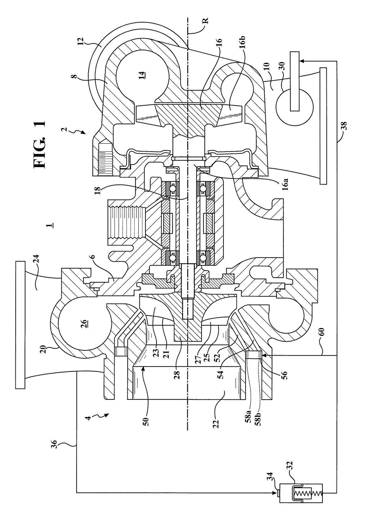
[0017]Referring to FIG. 1, an exhaust gas turbocharger 1 includes a turbine stage 2, a compressor stage 4, and a bearing housing 6 disposed between and connecting the compressor stage 4 to the turbine stage 2. The turbine stage 2 includes a turbine housing 8 that defines an exhaust gas inlet 10, an exhaust gas outlet 12, and a turbine volute 14 disposed in the fluid path between the exhaust gas inlet 10 and the exhaust gas outlet 12. An axial-flow turbine wheel 16 is disposed in the turbine housing 8 between the turbine volute 14 and the exhaust gas outlet 12. The axial-flow turbine wheel 16 has a hub 16a and a plurality of axial-flow turbine blades 16b configured to rotate the turbine wheel 16 and a centrally attached rotatable shaft 18 when the turbocharger 1 receives exhaust gas flow from the engine. In some embodiments, the hub 16a is a low-stress small hub attached to the rotatable shaft 18 by conventional methods. The shaft 18 is rotatably supported within the bearing housing ...


PUM


Abstract

A turbocharger (1) with an axial flow turbine stage (2) includes a compressor stage (4) using active casing treatment (50) for choke flow improvement. With switchable slots (52, 54), one of the slots (52) may be between the compressor's full and splitter blades (27, 23) and one of the slots (54) can be located downstream of the compressor's splitter blades (23) to maximize choke flow capacity. In turbochargers with a wastegate assembly, a pneumatic actuator (32) may control both a wastegate control valve (30) and an active casing treatment slot selection valve (56).

Description

CROSS-REFERENCE TO RELATED APPLICATION[0001]This application claims priority to and all the benefits of U.S. Provisional Application No. 61 / 857,868, filed on Jul. 24, 2013, and entitled “Turbocharger Combining Axial Flow Turbine with a Compressor Stage Utilizing Active Casing Treatment,” the contents of which are incorporated by reference herein.BACKGROUND[0002]1. Field of the Disclosure[0003]This disclosure relates to axial or highly mixed flow turbochargers. More particularly, this disclosure relates to a turbocharger that combines an axial flow turbine with a compressor stage using Active Casing Treatment.[0004]2. Description of Related Art[0005]In exhaust gas turbocharging, some of the exhaust gas energy resulting from combustion in an internal combustion engine, which would normally be wasted, is used to drive a turbine. The turbine includes a turbine wheel that is mounted on a shaft and is rotatably driven by exhaust gas flow. The turbocharger returns some of this normally was...

Claims


Application Information

Patent Timeline
Patent Type & Authority Patents(United States)
IPC IPC(8): F04D29/66F02B37/18F02C6/12F04D27/02F04D29/42F04D29/68
CPCF02C6/12F02B37/183F04D27/0207F04D27/0246F04D29/4213F04D29/685F04D27/0238F05D2220/40Y02T10/12
Inventor MCGAHEY, MICHAEL E.AUSBROOKS, MICHAEL
Owner BORGWARNER INC
Why Eureka
Try Eureka