
Beam splitters

a beam splitter and beam technology, applied in the field of atomic physics and quantum physics, can solve the problems of limiting the coherence time of atoms in such types of magnetic traps, low power, high performance and low cost, and achieves superior performance, longer interrogation times, and small devices.

Active Publication Date: 2019-05-21
NPL MANAGEMENT
View PDF3 Cites 0 Cited by
  • Summary
  • Abstract
  • Description
  • Claims
  • Application Information

AI Technical Summary

Benefits of technology

The patent describes a new technology for creating continuous beam splitters, which can be used in interferometers to measure parameters like accelerations and rotations. This technology offers higher accuracies and smaller size compared to traditional non-quantum based products like ring laser gyroscopes and fibre optic gyroscopes. It is important for applications where there need to be no dead times when information is lost. The cold atom gyroscopes offer similar sensitivity to rotation at a much smaller size of the device because of their large mass.

Problems solved by technology

The main problem of these beam splitters is that they work only for magnetically trappable atoms.
In addition, the local fluctuations of the surface electric currents, which are used to form the trapping magnetic field, limit the coherence time of the atoms in such types of magnetic traps, unless the current-carrying substrate is cooled down to cryogenic temperatures.
A technical challenge, therefore, is to design and build atom interferometer based devices with unprecedented small size, light weight, low power, high performance and low cost characteristics.

Method used


Image

  • Beam splitters
  • Beam splitters
  • Beam splitters

Examples


Embodiment Construction

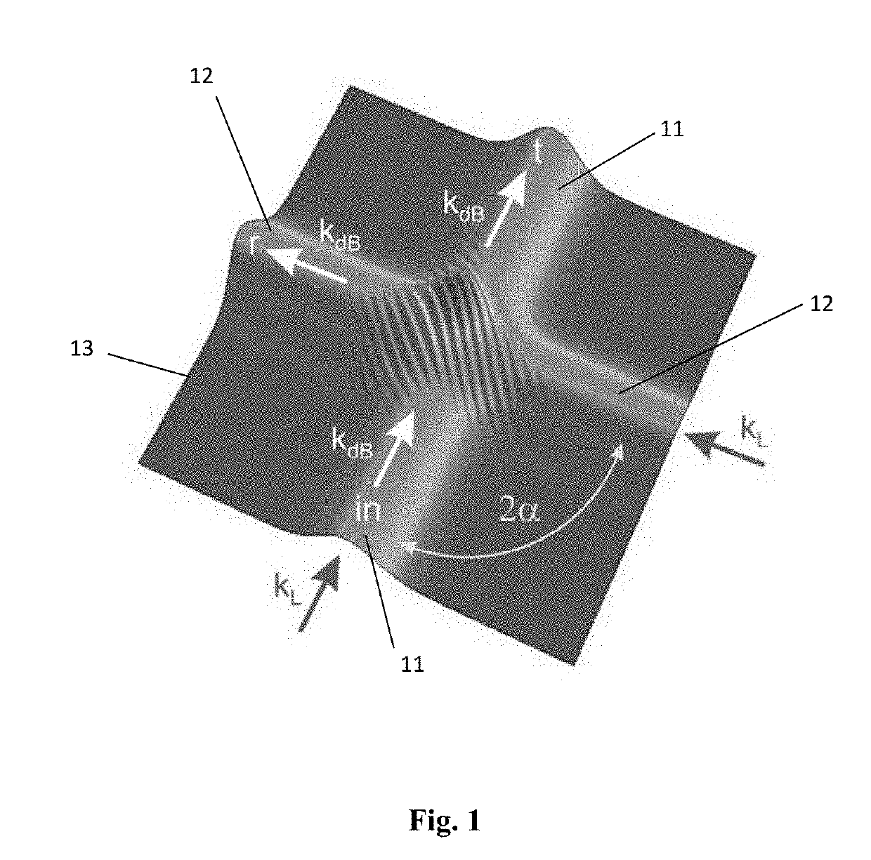
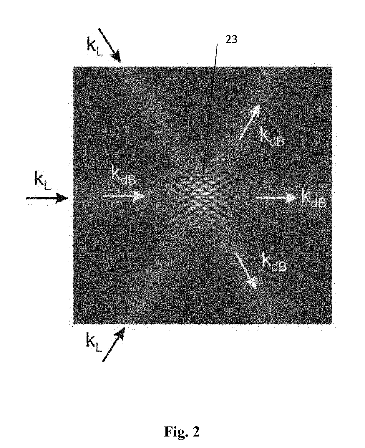
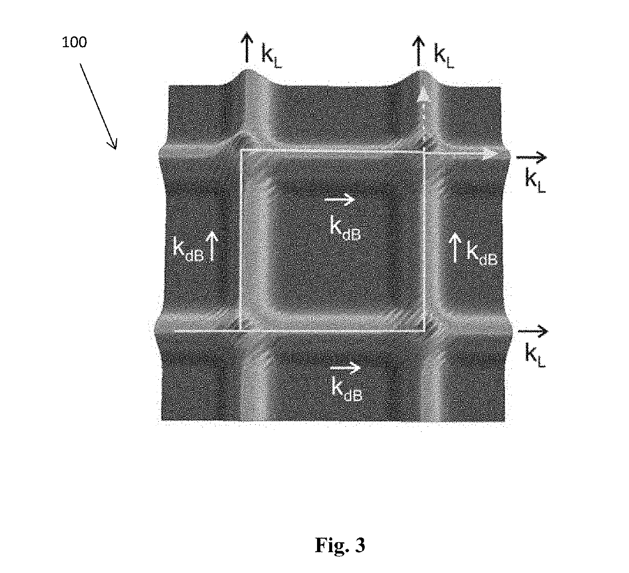
[0066]Referring firstly to FIG. 1, we are considering waveguides for matter waves, which are formed by focussed laser beams, both labelled kL in FIG. 1, the frequency of which is detuned sufficiently far above or below one of the internal atomic transitions of the matter waves so as not to induce such an atomic transition. Such a waveguide can be single-mode or multimode, which depends on the intensity and diameter of the laser beam.

[0067]Consider two such identical waveguides, labelled 11 and 12 in FIG. 1, which intersect each other at an angle of 2α in a region labelled 13. The interference of the laser beams in the region 13 of their intersection produces a standing light wave, the angle of which with respect to the waveguides is exactly equal to ±α and its period is equal to d=π / k / sin α, where k=2π / λ is the wave vector of the laser field. The amplitude of the standing wave depends on a degree of interference between the crossed laser beams and can be accurately tuned by their mu...


PUM


Abstract

A temporally continuous matter wave beam splitter (14) comprising a plurality of intersecting and interfering laser beam (kr, kb), which act as waveguides for a matter wave beam. The laser beams of the waveguides each have a frequency detuned below a frequency of an internal atomic transition of the matter wave. The matter wave has a wavevector which is an integral multiple of the wavevector of the laser beams within a region of intersection of the laser beams. There is also provided an atomic interferometer (200) comprising such a continuous matter wave beam splitter, and a solid state device comprising such a continuous matter wave beam splitter, which may be part of an atomic interferometer. A cold atom gyroscope, a cold atom accelerometer or a cold atom gravimeter comprising such a solid state device are also provided. There is further provided a quantum computer comprising such a solid state device, wherein atoms of the matter wave beam are in an entangled quantum state. There is also provided a method of splitting a matter wave beam, comprising introducing the matter wave beam into a first temporally continuous laser beam, the frequency of which is detuned below a frequency of an internal atomic transition of the matter wave beam; intersecting and interfering the first continuous laser beam with a second temporally continuous laser beam, the frequency of which is also detuned below the frequency of the internal atomic transition of the matter wave beam; providing the matter wave beam with a wavevector which is an integral multiple of the wavevector of the first and second laser beams within a region of intersection of the laser beams, whereby the laser beams act as waveguides for the matter wave beam.

Description

TECHNICAL FIELD[0001]The present invention is in the field of atomic physics and quantum physics, and more particularly, atomic interferometry and matter wave interferometry. In particular, it relates to beam splitters and especially to waveguide diffraction beam splitters for matter waves based on crossed interfering laser beams and matter wave interferometry using such beam splitters.BACKGROUND ART[0002]The main interest in matter wave interferometers is based on the very high sensitivity of these interferometers to accelerations (including gravitation and rotations) and electromagnetic fields, as described, for example, in A. D. Cronin, J. Schmiedmayer, D. E. Pritchard, “Optics and interferometry with atoms and molecules”, Rev. of Mod. Phys. 81, 1051 (2009) (hereinafter called [Ref 1]). Most existing atom interferometers are based on free propagating atoms, which are coherently split by mechanical gratings or non-resonant standing light waves [Ref 1]. On the other hand, there is ...

Claims


Application Information

Patent Timeline
Patent Type & Authority Patents(United States)
IPC IPC(8): G21K1/00H05H3/04G01P15/02G01C19/02G21K1/06G01V7/00
CPCG21K1/006G01C19/02G01P15/02G21K1/067H05H3/04G21K1/06G01V7/00
Inventor OVCHINNIKOV, YURI BORISOVICH
Owner NPL MANAGEMENT
Learn More