
Connection device, pipes incorporating same for fluid transmission piping of an aircraft or a spacecraft, and method for manufacturing said device

a technology for fluid transmission pipes and connecting devices, which is applied in the direction of packaging foodstuffs, bends, packaged goods, etc., can solve the problems of limited electrostatic charge accumulation in the piping traveled through by the fuel, the connection surface is not electrically conductive, and the risk of explosion, so as to reduce the assembly time of fuel lines

Active Publication Date: 2019-06-04
HUTCHINSON SA
View PDF13 Cites 3 Cited by
  • Summary
  • Abstract
  • Description
  • Claims
  • Application Information

AI Technical Summary

Benefits of technology

The patent text describes a method for controlling the electrical conductivity of an aircraft's airfoil to prevent fuel explosions caused by lightning strike. To ensure safety, the method also reduces electrostatic charges within the piping that may lead to pressure loss or cavitation in the flow of transported fluids. Additionally, the method addresses the issues of thermoplastic tips filled with fibers by ensuring smooth and cylindrical joints without weld lines or other mold "parting". The overall effect of this method is to improve safety and reduce manufacturing costs.

Problems solved by technology

Indeed, it is necessary to ensure, during a lightning strike, that on the one hand the lightning flows primarily through the structures of the wings, and on the other hand the accumulation of electrostatic charges inside the piping traveled through by the fuel is strictly limited to avoid any risk of explosion by inflammation of the fuel.
One major drawback of these known cylindrical links is that the slippery coatings deposited on the machined connectors cause the connecting surfaces not to be electrically conductive.
However, the tendency toward corrosion of the aluminum requires protecting these connectors using surface treatments, for example of the Chromic Anodic Oxidation (CAO) type and also in the stepped zones of the sealing gaskets by slippery surface treatments which, as explained above, do not conduct the current.
One major drawback of these conductive braids is that they extend the assembly time, increase the risks of incorrect assembly, and raise the overall manufacturing and assembly costs and the weight of the pipes.
With the arrival of composite wings and the risk of lightning preferably passing through the fuel pipes, these machined and treated aluminum connectors, even though their surfaces are insulating, have excessively high electrical conductivity in their mass to prevent any passage of lightning in the piping.
One major drawback of these electrically insulating tubings inserted between the tubes of the piping lies in the high number of additional parts, which are expensive and make the aircraft still heavier.
One drawback of these insulating joints lies in the need to attach metal braids on the tubes and / or on the connectors to allow electrical continuity between connectors and tubes and with the adjacent structure, so as to discharge the electrostatic charges toward that structure.
It will further be noted that the use of such a connection device essentially made up of this thermoplastic matrix tip was not possible at this time in the aeronautic industry, due to:excessively high required mechanical properties, in particular the vibrational rigidity,the impossibility of allowing any creep in the tip, unacceptable to guarantee tightness of the cylindrical links over time, andthe lack of electrical conductivity of thermoplastics.
If one instead chose to increase the mechanical characteristics of a thermoplastic for example by filling it with short glass fibers, the obtained mechanical characteristics would be too weak to contribute to an aluminum machined in the mass.
Advantageously, the pipe may not have any electrically insulating tubing between the tubes.
Yet machining to resolve this, in light of the presence of machined fibers on the surface, would cause premature wear of the joints in terms of endurance and would significantly increase the manufacturing cost of the parts.
However, this solution is expensive in terms of tooling and may be difficult to mechanize due to a bulk of the cylinders or other mechanisms in the mold.

Method used


Image

  • Connection device, pipes incorporating same for fluid transmission piping of an aircraft or a spacecraft, and method for manufacturing said device
  • Connection device, pipes incorporating same for fluid transmission piping of an aircraft or a spacecraft, and method for manufacturing said device
  • Connection device, pipes incorporating same for fluid transmission piping of an aircraft or a spacecraft, and method for manufacturing said device

Examples


Embodiment Construction

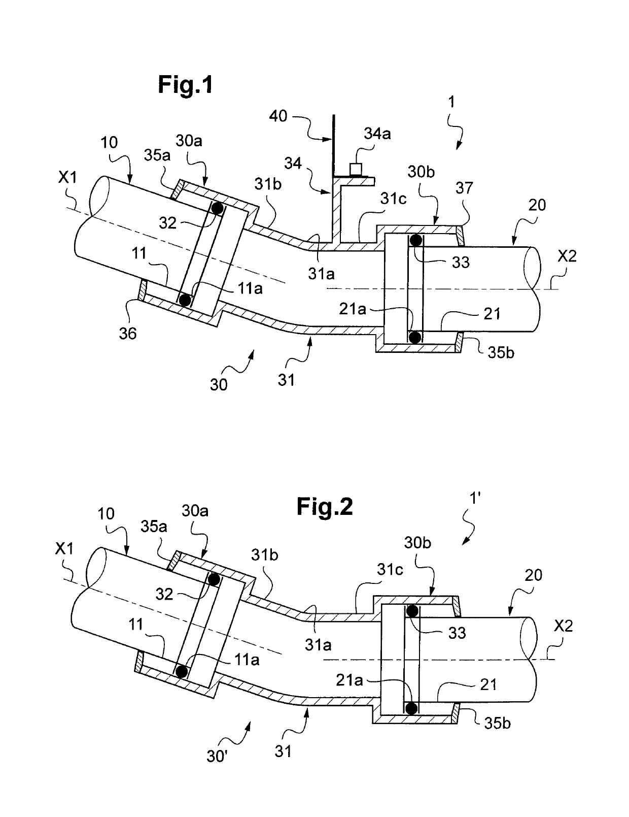
[0077]A pipe 1, 1′ according to the examples of the invention shown in FIGS. 1 and 2 is for example intended to convey an aircraft fuel, and it is made up of two tubes 10, 20 that are preferably nonmetallic and a connection device 30, 30′ that connects them to one another directly via sliding and rolling links in two respective end zones 30a and 30b of the device 30, 30′, and optionally furthermore connects the tubes 10 and 20 to a fuel tank 40 (see FIG. 1). In both of these cases, this device 30, 30′ is made up of an injection-molded tip 31 of the composite type with a thermoplastic matrix having a bent or curved central zone 31a, and two electrically insulating annular sealing gaskets 32 and 33 that are mounted radially between and in contact with two respective end zones 11 and 30a, 21 and 30b of the tubes 10 and 20 and the tip 31.

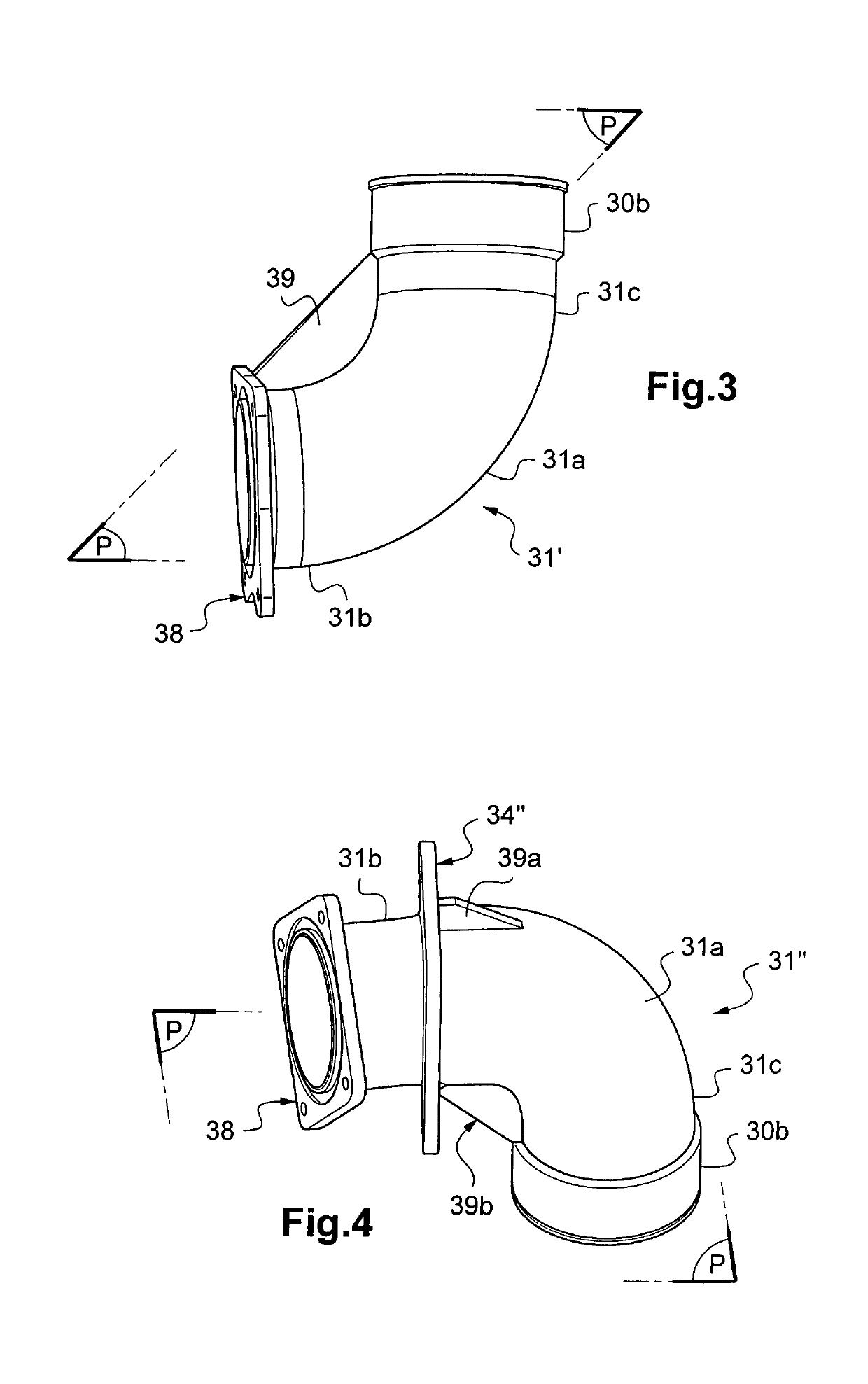
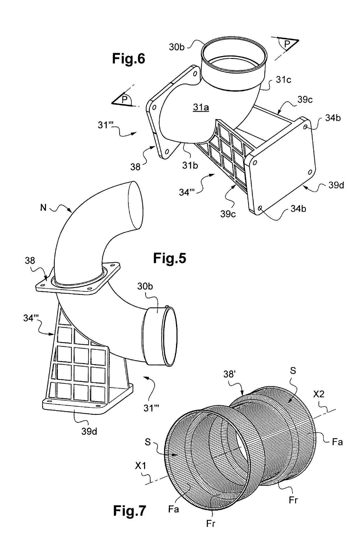
[0078]In general, the tip 31 according to the invention has an axial mold parting plane P (shown in FIGS. 3, 4 and 6), which corresponds to the median ...


PUM

PropertyMeasurementUnit
Fractionaaaaaaaaaa
Fractionaaaaaaaaaa
Fractionaaaaaaaaaa

Abstract

A connection device is suitable for connecting two tubes to one another, and optionally to a fluid tank for fluid transmission piping of an aircraft or a spacecraft Also disclosed are pipes incorporating said tubes and said device; and a method for manufacturing said device. The device includes an injection-molded tip that has at least one angled or inwardly curved area and is made of a composite material with a thermoplastic matrix reinforced by a reinforcement system including carbon fibers. The tip has a median longitudinal mold parting plane (P). The carbon fibers extend so as to be oriented along the tip, which incorporates mechanical and vibratory stiffening means which are integrally molded with the tip and lie in said parting plane or symmetrically relative to said plane in said at least one area and / or immediately near said area.

Description

CROSS-REFERENCE TO RELATED APPLICATION[0001]This application is a National Stage of WOSN PCT / FR2013 / 052649, filed Nov. 6, 2013.FIELD OF THE INVENTION[0002]The present invention relates to a connection device between two tubes, and optionally furthermore to a fluid tank for transmission piping of this fluid in an aircraft or a spacecraft, pipes for such a piping incorporating these tubes and this connection device connecting them to one another, and method for manufacturing this device. The invention in particular applies to piping of a fuel circuit of a civilian or military aircraft, in particular equipped with composite wings, having specified that it generally relates to connections and fastenings of all fluid transfer tubes, for example for fuel, water production, wastewater discharge, drainage, oxygen or cooling circuits, non-limitingly.BACKGROUND OF THE INVENTION[0003]Document WO-A1-2011 / 007100 discloses connecting devices between metal tubes intended to protect an aircraft fue...

Claims


Application Information

Patent Timeline
IPC IPC(8): F16L43/00F16L57/00A45D34/04C08L83/10C08G77/442A61Q1/04A61K8/92A61K8/895A61K8/891
CPCF16L43/008A45D34/042A61K8/891A61K8/895A61K8/92A61Q1/04C08L83/10F16L57/00C08G77/442A61K2800/87A45D34/045A45D2200/055A45D2200/1018A61K2800/544F16L43/00F16L9/12
Inventor GONZALEZ BAYON, CRISTINABERGERE, STEPHANEFLORENTZ, BERTRAND
Owner HUTCHINSON SA
Learn More