Piston ring-belt structural reinforcement via additive machining

a technology of additive manufacturing and piston rings, applied in the direction of machines/engines, manufacturing tools, mechanical apparatus, etc., to achieve the effects of reducing blow-by, reducing thermal and mechanical distortion of piston rings, and increasing piston rings performan

Active Publication Date: 2019-06-11
TENNECO INC
View PDF15 Cites 0 Cited by
  • Summary
  • Abstract
  • Description
  • Claims
  • Application Information

AI Technical Summary

Benefits of technology

[0005]One aspect of the invention comprises a piston for an internal combustion engine. The piston includes an insert providing for reduced thermal and mechanical distortion of a ring belt, and thus increased piston ring performance, reduced blow-by, and ultimately improved engine emissions. The piston includes a body formed of a metal material. The body includes an upper combustion surface and an oppositely facing undercrown surface. The body also includes a ring belt extending from the upper combustion surface and having a plurality of ring grooves. The body also includes a pair of pin bosses extending from the undercrown surface. The piston further includes the insert extending radially from an inner surface of the ring belt to the undercrown surface or radially from an inner surface of the ring belt to one of the pin bosses for supporting the ring belt. The insert is formed by an additive machining process.
[0006]Another aspect of the invention provides a method of manufacturing a piston for an internal combustion engine which includes an insert providing for a reduced thermal and mechanical distortion of a ring belt, and thus increased piston ring performance, reduced blow-by, and ultimately improved engine emissions. The method includes providing a body formed of a metal material, the body including an upper combustion surface and an oppositely facing undercrown surface, the body including a ring belt having a plurality of ring grooves and extending from the upper combustion surface, and the body including a pair of pin bosses extending from the undercrown surface. The method further includes forming the insert extending radially from an inner surface of the ring belt to the undercrown surface or radially from the inner surface of the ring belt to one of the pin bosses for supporting the ring belt. The step of forming the insert includes an additive machining process.

Problems solved by technology

The blow-by is typically a result of improper compression ring seating due to thermal and mechanical distortion of the ring belt geometry and includes leakage of an air-fuel mixture or combustion gases between the piston and the cylinder wall into the crankcase.

Method used


Image

  • Piston ring-belt structural reinforcement via additive machining
  • Piston ring-belt structural reinforcement via additive machining
  • Piston ring-belt structural reinforcement via additive machining

Examples


Embodiment Construction

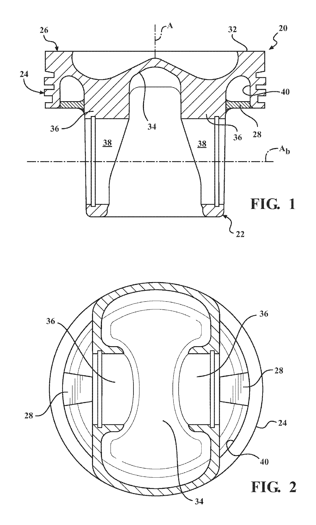
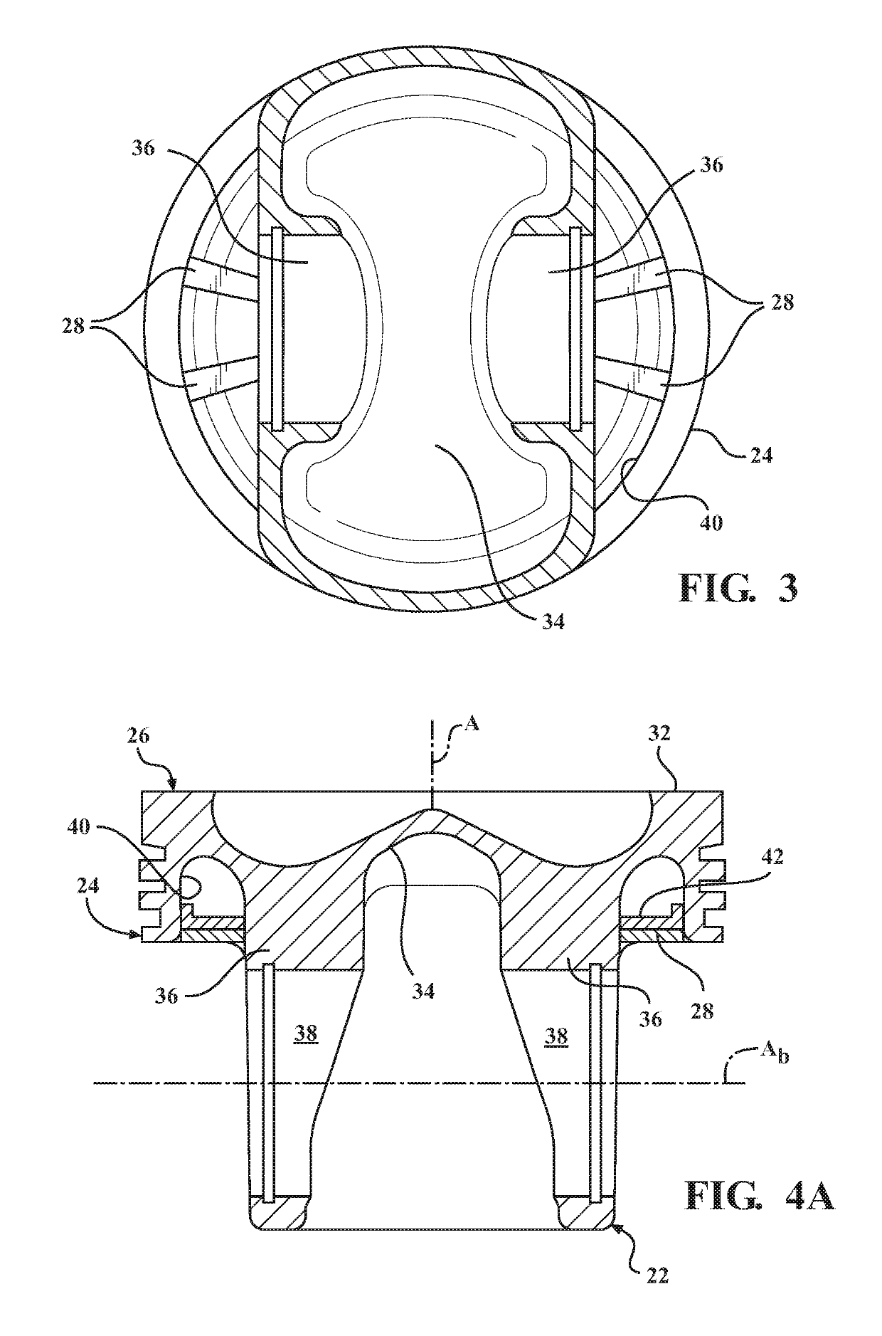
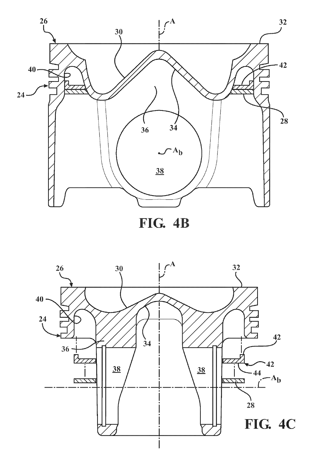
[0015]A piston 20 for an internal combustion engine according to example embodiments is generally shown in FIGS. 1-4D. The piston 20 comprises a body 22 with a ring belt 24 extending form an upper combustion surface 26, and an insert 28 formed by an additive machining process. The insert 28 supports the ring belt and thus provides for reduced thermal and mechanical distortion of the ring belt 24, and thus increased piston ring performance, reduced blow-by, and ultimately improved engine emissions.

[0016]The body 22 of the piston 20 is formed of a first material, which is typically from a steel material, an aluminum-based material, and cast iron. In the example embodiments, the body 22 of the piston 20 is a single-piece and is referred to as a galleryless piston. Alternatively, the body 22 of the piston 20 can be designed as a two-piece articulated piston, or the body 22 could have another design.

[0017]The body 22 includes the upper combustion surface 26 surrounding a center axis A fo...


PUM

PropertyMeasurementUnit
strengthaaaaaaaaaa
velocityaaaaaaaaaa
weightaaaaaaaaaa

Abstract

A piston including at least one insert disposed between an inner surface of a ring belt and undercrown surface, and / or between the inner surface of the ring belt and a pin boss, to provide reinforcement to the ring belt is provided. The insert reduces thermal and mechanical distortion of the ring belt, and thus increases the piston ring performance, reduces blow-by, and ultimately improves engine emissions. The insert is formed by an additive machining process, such as direct depositing, laser cladding, laser sintering, arc welding, additive welding, plasma transferred arc spraying, plasma welding, arc welding, selective laser sintering, and high velocity oxygen fuel spraying, plasma spraying. According to one embodiment, an intermediate piece is mechanically attached to the piston, and the insert is applied to the intermediate piece, to provide additional reinforcement.

Description

BACKGROUND OF THE INVENTION1. Field of the Invention[0001]This invention relates generally to pistons for internal combustion engines, and methods for manufacturing the pistons.2. Related Art[0002]Engine manufacturers are encountering increasing demands to improve engine efficiencies and performance, including, but not limited to, improving fuel economy, reducing oil consumption, improving fuel systems, increasing compression loads and operating temperatures within the cylinder bores, reducing heat loss through the piston, improving lubrication of component parts, decreasing engine weight and making engines more compact, while at the same time decreasing the costs associated with manufacture.[0003]In order to provide a piston with reduced weight, reduced manufacturing costs, and reduced compression height, the pistons are often designed as a single-piece without a closed cooling gallery along an undercrown surface. These pistons are typically referred to as “galleryless” pistons. An...

Claims


Application Information

Patent Timeline
Patent Type & Authority Patents(United States)
IPC IPC(8): F02F3/00B33Y10/00C23C4/129C23C4/134B23K10/02B23K9/04B23K26/342B33Y80/00F02F3/08F02F3/26F02F3/22F02F3/02B23K101/00
CPCF02F3/0015B23K10/027B23K26/342B33Y10/00B33Y80/00C23C4/129C23C4/134F02F3/003F02F3/0084F02F3/02F02F3/08F02F3/22F02F3/26B23K9/044B23K2101/003
Inventor EVERS, ROSSWEISS, RAINERUNGERMANN, SVEN
Owner TENNECO INC
Why Eureka
Try Eureka