
Compac carbon ion LINAC

a carbon ion linac and linac technology, applied in the field of linacs, can solve the problems of not offering the flexibility of simple tuning of the time structure or the energy of the beam, and the damage of healthy parts of radiation, so as to reduce the average rf power required, the pulse length of the pulse is reduced, and the energy modulated ion beam therapy is fast.

Active Publication Date: 2019-07-23
UCHICAGO ARGONNE LLC
View PDF14 Cites 5 Cited by
  • Summary
  • Abstract
  • Description
  • Claims
  • Application Information

AI Technical Summary

Benefits of technology

[0019]Still another object of the invention is to provide a high efficiency linac. A feature of the invention is that it operates in the S-band frequency (e.g., frequencies around 3 GHz). An advantage of the invention is that this relatively higher frequency (compared to the lower frequencies of about 400 MHz of typical linacs) allows for higher voltage gradients and therefore shorter linacs. The invention enables therapeutic grade linacs with lengths of between about 30 and 50 meters; and typically 40 meters or less.
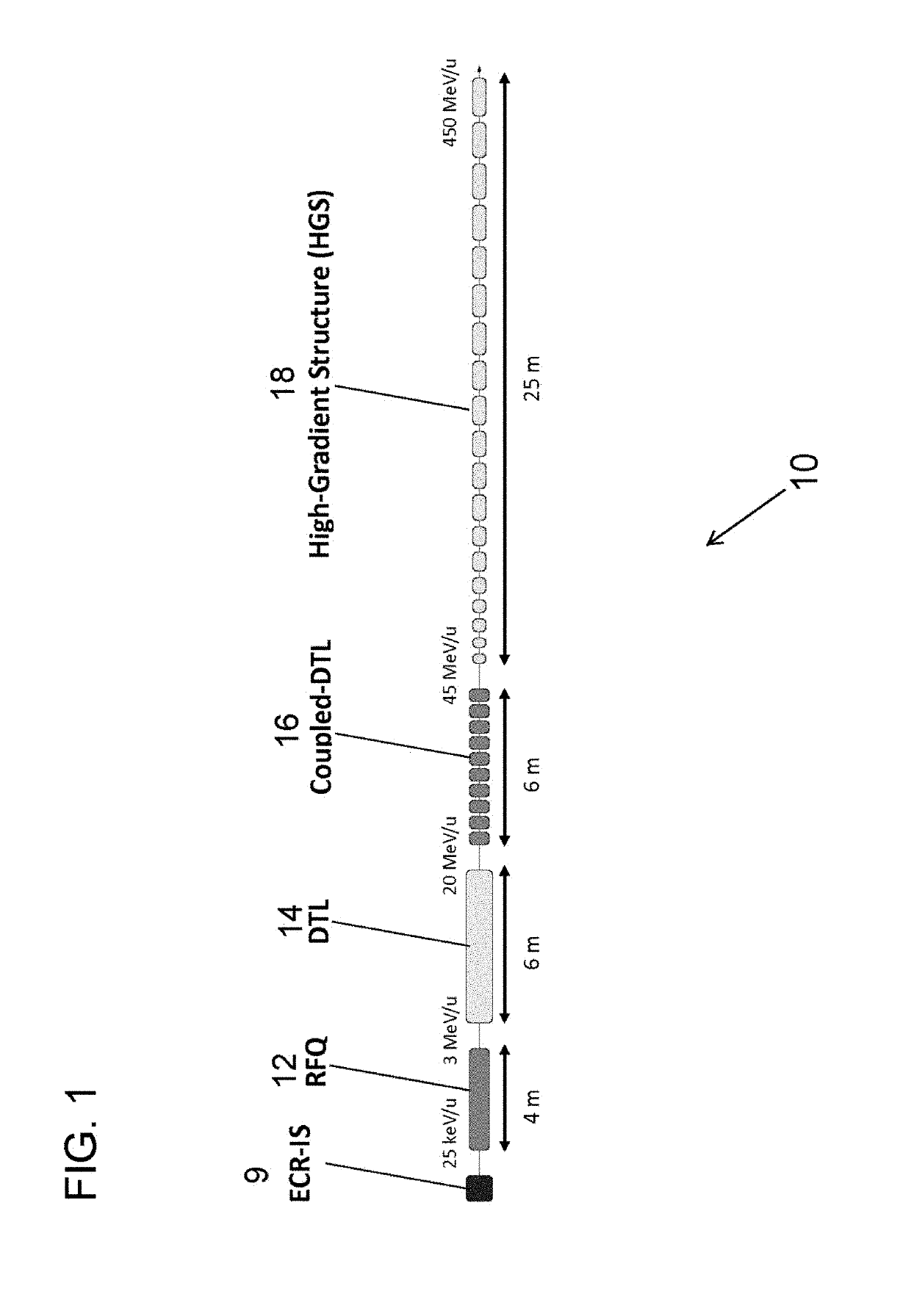
[0020]Yet another object of the present invention is to provide accelerating structures which cover velocity ranges from about 0.02 c to 0.8 c (where c is the speed of light). A feature of the invention is that it will provide 50 MV / m accelerating gradients. An advantage is the enablement of a 450 MeV / u accelerator for 12C6+ ions and 250 MeV for protons, with a compact footprint of about 8 meters by 30-45 meters, compared to a 25 meter×25 meter footprint of state of the art configurations.
[0021]Another object of the present invention is to provide a linac as short as 40 meters. A feature of the invention is that pulsed S-band room-temperature structures are capable of delivering a voltage gradient between about 40 and about 60 MV / m. An advantage of the invention is that the pulsed nature allows fast change in beam energy which could be done pulse-per-pulse up to about 400 Hz. Energy modulated ion beam therapy is therefore enabled.
[0022]Still another object of the present invention is to provide a carbon ion linac operating in the S-band frequency. A feature of the invention is that the delivered carbon ion beam intensity is adjusted by changing the pulse repetition rate of the beam energy, and the pulse duration. An advantage of the invention is that the short beam pulses, at between approximately 100 and approximately 1000 nanoseconds (ns), reduces RF pulse length and the average RF power required for acceleration. This increases the RF breakdown limit, thereby minimizing pitting, arcing, and other maladies plaguing low frequency structures. Peak surface electric fields exhibited are less than about 160 MV / m.
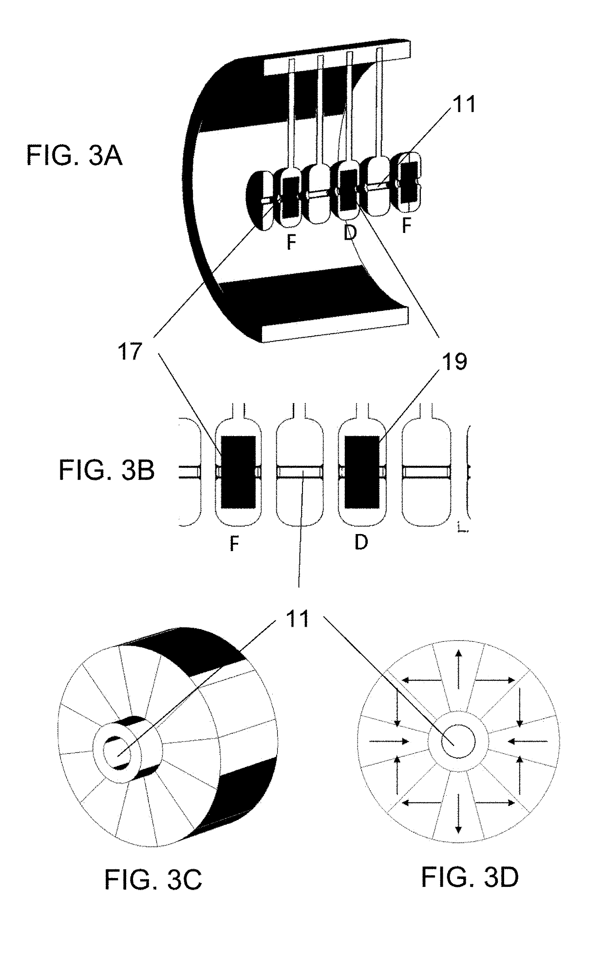
[0023]Another object of the present invention is providing a tunable linear accelerator. A feature of the invention is that although the drift tube linac utilizes constant field permanent magnets, the voltage in the cavities and current in the magnets is scaled, depending on the charge-to-mass ratio of the beam. An advantage is that the entire system can be tuned to accommodate different types of beams (e.g., carbon ions and protons).
[0024]Briefly, the invention provides a method for accelerating protons and carbon ions up to 450 MeV / u in a very compact linac, the method comprising subjecting the particles to a radio frequency quadrupole field to accelerate the particles to at least about 3 MeV / u, a drift tube linac (DTL) to an energy of 20 MeV / u, followed by a coupled DTL to 45 MeV / u and finally a high-gradient section made of CCL-type standing wave cavities or negative harmonic traveling wave cavities operating at S-band frequencies and capable of delivering voltage gradients of 40 to 60 MV / m. Focusing the accelerated particles while accelerated to higher energy is provided by appropriately placed permanent magnets and electromagnetic quadrupoles.

Problems solved by technology

However, these particles spread the dose over the entire volume of a target tissue, thereby creating radiation damage to healthy parts.
Both cyclotrons and synchrotrons are expensive and bulky constructions with large magnets.
It does not offer the flexibility of adjusting the time structure or the energy of the beam by simple tuning.
This process generates a large amount of radiation and significantly worsens the beam quality.
The effect is unnecessary beam loss and radiation that requires adequate shielding.
Synchrotrons are circular structures which require large magnets that consume large amounts of power.
Due to the multi-turn acceleration in a synchrotron, changing the energy may take a few seconds such that it is not effective for fast three dimensional tumor painting or treatment of moving organs.
This cannot be easily achieved in a synchrotron because of the multi-turn and cyclic nature of those machines.

Method used


Image

  • Compac carbon ion LINAC
  • Compac carbon ion LINAC
  • Compac carbon ion LINAC

Examples


example

[0116]A compact (8×45 meters) Advanced Compact Carbon Ion Linac was developed, capable of providing 50 MV / m for particles with a beta of from about 0.3 to about 0.7. The high operating gradients are enabled by operation at high frequency (e.g., 2856 MHz), at very low duty cycle (e.g., less than 0.06 percent) and for very short (less than 0.5 microsecond) beam pulses. The duty cycle is the product of the pulse length multiplied by the repetition rate, so one may have a relatively long pulse at a very low repetition rate.

[0117]Since all ion species will have the same velocity or energy per nucleon at any given point in the linac, a specific example of the carbon beam is provided here. The results shown in FIG. 5A were obtained using the beam dynamics code TRACK, locally developed at ANL. The sequence of the beam line element as well as their appropriate voltage and current settings are used as input to the code.

[0118]The 12C5+ beam is extracted from the ion source (not shown) and inje...


PUM


Abstract

The invention provides a method for accelerating protons and carbon ions up to 450 MeV / u in a very compact linac, the method comprising subjecting the particles to a radio frequency quadrupole field to accelerate the particles to at least 3 MeV / u, a drift tube linac (DTL) to an energy of 20 MeV / u, followed by a coupled DTL to 45 MeV / u and finally a high-gradient section made of CCL-type standing wave cavities or negative harmonic traveling wave cavities operating at S-band frequencies and capable of delivering voltage gradients of 40 to 60 MV / m. Focusing the accelerated particles while accelerated to higher energy is provided by appropriately placed constant field permanent magnets and electromagnetic quadrupoles. The compactness and power efficiency of the linac is enabled by using high-gradient structure in the S-band frequencies for lower energy particles than ever before. The low-intensity required for hadron therapy allows the use of small-aperture S-band structures and the operation at very high gradient compared to high-intensity machines for research. Operating with very short sub-microsecond pulses at repetition rates up to 400 Hz allows the fast and flexible beam energy and intensity tuning not provided by existing hadron therapy machines. The designed linac is capable of accelerating ions as heavy as neon to the full 450 MeV / u energy, therefore allowing fast beam switching if different ion sources are installed in the front-end of the linac.

Description

PRIORITY[0001]This utility patent application claims priority benefit as a Non-Provisional of U.S. Provisional Patent Application No. 62 / 511,253, filed on May 25, 2017, the entirety of which is incorporated herein by reference.CONTRACTUAL ORIGIN OF THE INVENTION[0002]The U.S. Government has rights in this invention pursuant to Contract No. DE-AC02-06CH11357 between the U.S. Department of Energy and UChicago Argonne, LLC, representing Argonne National Laboratory.BACKGROUND OF THE INVENTION[0003]1. Field of the Invention[0004]This invention relates to LINACs and more specifically this invention relates to a compact system and method to accelerate particles toward a physiological target or a non-physiological target.[0005]2. Background of the Invention[0006]Ion beam therapy is becoming a standard of care for treatment of tumors. Approximately one third of the world's 15,000 accelerators are used for tumor therapy and other medical applications.[0007]There are currently three technologi...

Claims


Application Information

Patent Timeline
Patent Type & Authority Patents(United States)
IPC IPC(8): A61N5/10H05H7/22H05H7/02H05H9/04H05H7/04
CPCH05H7/22H05H7/02H05H7/04H05H9/042H05H9/044H05H9/045H05H2277/11A61N5/1043A61N2005/1087H05H2007/025H05H2007/043H05H2007/222
Inventor MUSTAPHA, BRAHIMNASSIRI, ALIREZAOSTROUMOV, PETER N.PLASTUN, ALEXANDER S.GOEL, ADITYA
Owner UCHICAGO ARGONNE LLC
Learn More