Synchronized true random number generator
a true random number generator and synchronized technology, applied in the field of true random number generators, can solve the problems of limiting the speed at which thermal noise sources can be sampled, the inability to accurately predict the thermal noise of resistors of macroscopic scale, and the fundamental change of time in a fundamental way, so as to achieve the most convenient use, good statistical properties, and high temporal accuracy
- Summary
- Abstract
- Description
- Claims
- Application Information
AI Technical Summary
Benefits of technology
Problems solved by technology
Method used
Image
Examples
example 1
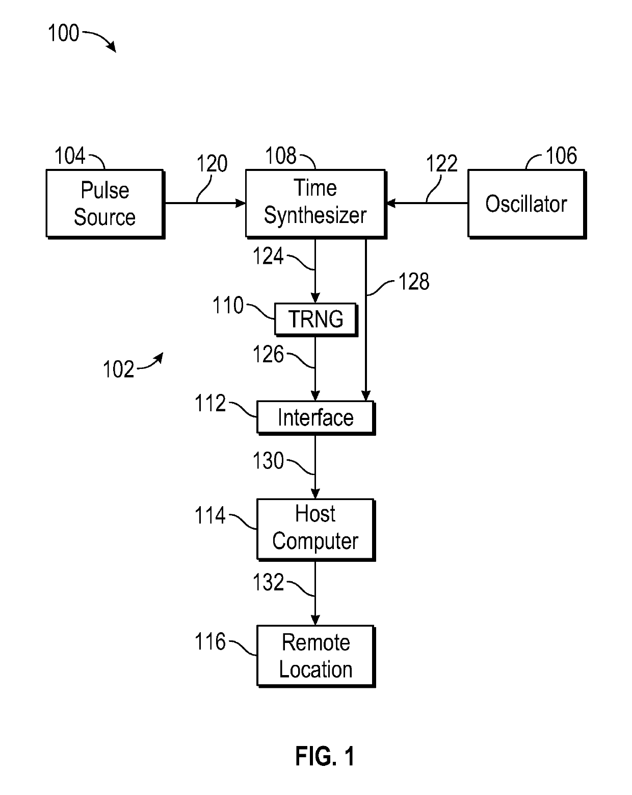
[0040]An exemplary embodiment of a synchronized random number generator in accordance with the invention is described here with reference to FIG. 1. A SRNG 102 included a standalone pulse source 104 of a 1PPS signal synchronized with UTC, namely, a GPS timeserver. 1PPS pulse signal 120 was provided as an input to time synthesizer 108, here a Field Programmable Gate Array (FPGA). FPGA time synthesizer 108 also received a clock signal 122 from high-precision 20 MHz temperature compensated crystal oscillator (TCXO) 106. A phase-locked loop (PLL) frequency multiplier in the FPGA produced a 128 MHz system clock signal using 20 MHz oscillator signal 122. This system clock was used to produce a one cycle per second (1CPS) signal that was locked to the 1PPS signal. Because 20 MHz oscillator 106 has some deviation from the exact specified frequency, the system clock signal typically deviated from the exact specified frequency. An algorithm in time synthesizer 108 (FPGA firmware) added or rem...
example 2
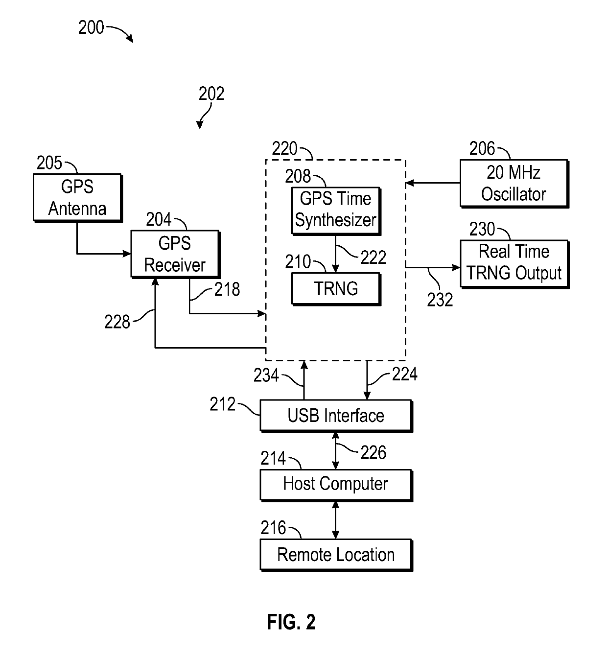
[0047]An exemplary embodiment of a synchronized random number generator system in accordance with the invention is described here with reference to FIG. 2. FIG. 2 contains a block diagram 200 of a preferred embodiment of a synchronized true random number generator system 202 in accordance with the invention that includes a GPS receiver.
[0048]SRNG system 202 comprised a GPS receiver 204, which was configured to receive a signal from a GPS antenna 205. SRNG system 202 also comprised high-precision 20 MHz temperature-compensated crystal oscillator (TCXO) 206, a GPS time synthesizer 208, a true (nondeterministic) random number generator (TRNG) 210, and a USB interface 212. As depicted in FIG. 2, interface 212 served to interface with a host computer 214. Host computer 214 was configured to communicate data to remote location 216.
[0049]GPS receiver 204 provided a complete UTC timestamp and GPS coordinates as well as a 1PPS signal. In addition, GPS receiver 204 provided information about ...
PUM
 Abstract
Description
Claims
Application Information
 - R&D
- Intellectual Property
- Life Sciences
- Materials
- Tech Scout
- Unparalleled Data Quality
- Higher Quality Content
- 60% Fewer Hallucinations
Browse by: Latest US Patents, China's latest patents, Technical Efficacy Thesaurus, Application Domain, Technology Topic, Popular Technical Reports.
© 2025 PatSnap. All rights reserved.Legal|Privacy policy|Modern Slavery Act Transparency Statement|Sitemap|About US| Contact US: help@patsnap.com


