
Soundproofing structure, opening structure, cylindrical structure, window member, and partition member

a soundproofing structure and cylindrical structure technology, applied in the direction of walls, instruments, constructions, etc., can solve the problems of increasing the number of components, the difficulty of widening the band in order to use resonance, and the size of the soundproofing structure, so as to ensure ventilation properties, high soundproofing performance, and light transmittance

Active Publication Date: 2019-08-06
FUJIFILM CORP
View PDF20 Cites 8 Cited by
  • Summary
  • Abstract
  • Description
  • Claims
  • Application Information

AI Technical Summary

Benefits of technology

The solution provides effective soundproofing across a broad frequency band, reduces material volume and weight, ensures ventilation, and maintains light transmittance, while being suitable for use in various environments without contaminating sensitive spaces.

Problems solved by technology

Further, as a principle, it is difficult to widen the band in order to use resonance.
In order to solve such a problem, it has been attempted to provide a plurality of holes in a thickness direction or a horizontal direction or provide a plurality of spaces on the rear surface, but there are problems of an increase in size of the soundproofing structure because a plurality of cells need to be provided, complication of the structures or components because these need to be formed separately, and an increase in number of components.
Further, since a closed space is required to be provided on the rear side, there are problems in that the size of the volume of the closed space is increased and the ventilation properties or waste heat cannot be ensured.
Therefore, there are problems in that the soundproofing performance higher than the mass law cannot be obtained and a sound cannot be satisfactorily absorbed because the sound is reflected.

Method used


Image

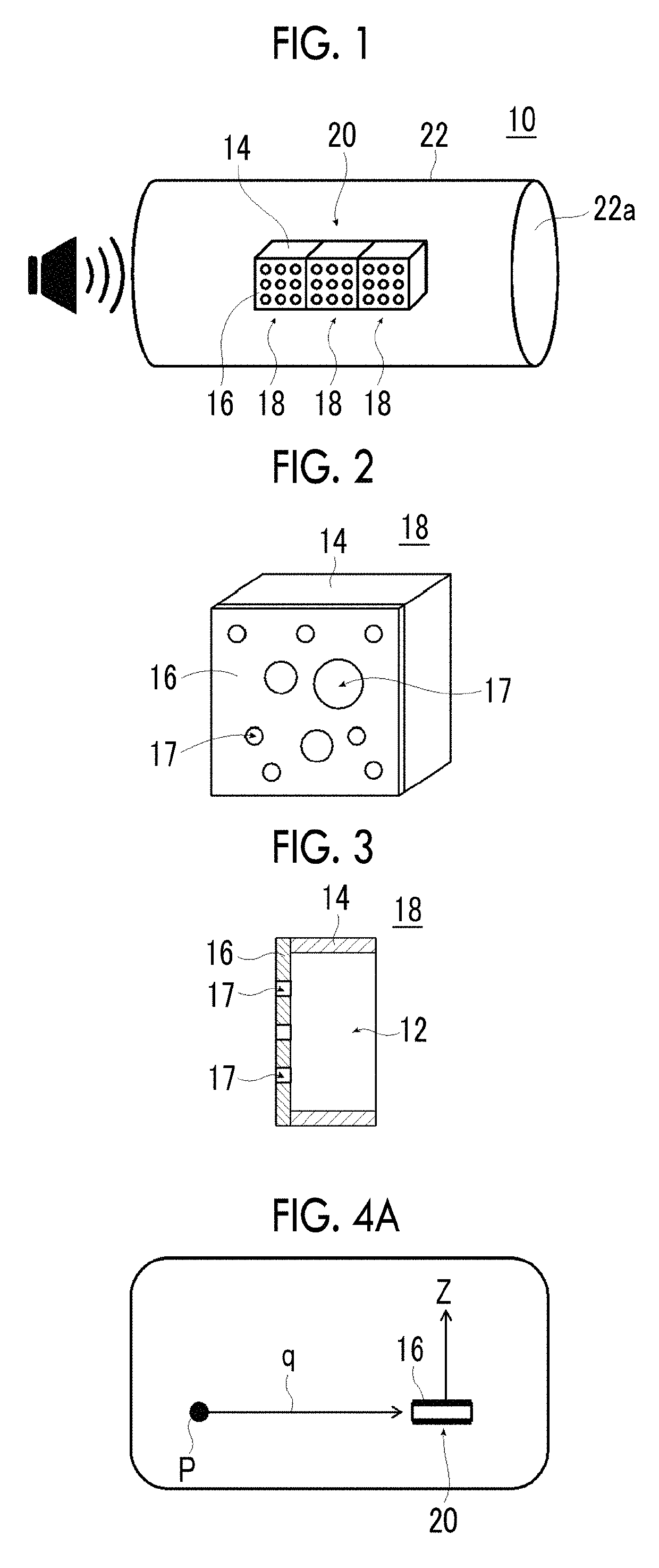
  • Soundproofing structure, opening structure, cylindrical structure, window member, and partition member
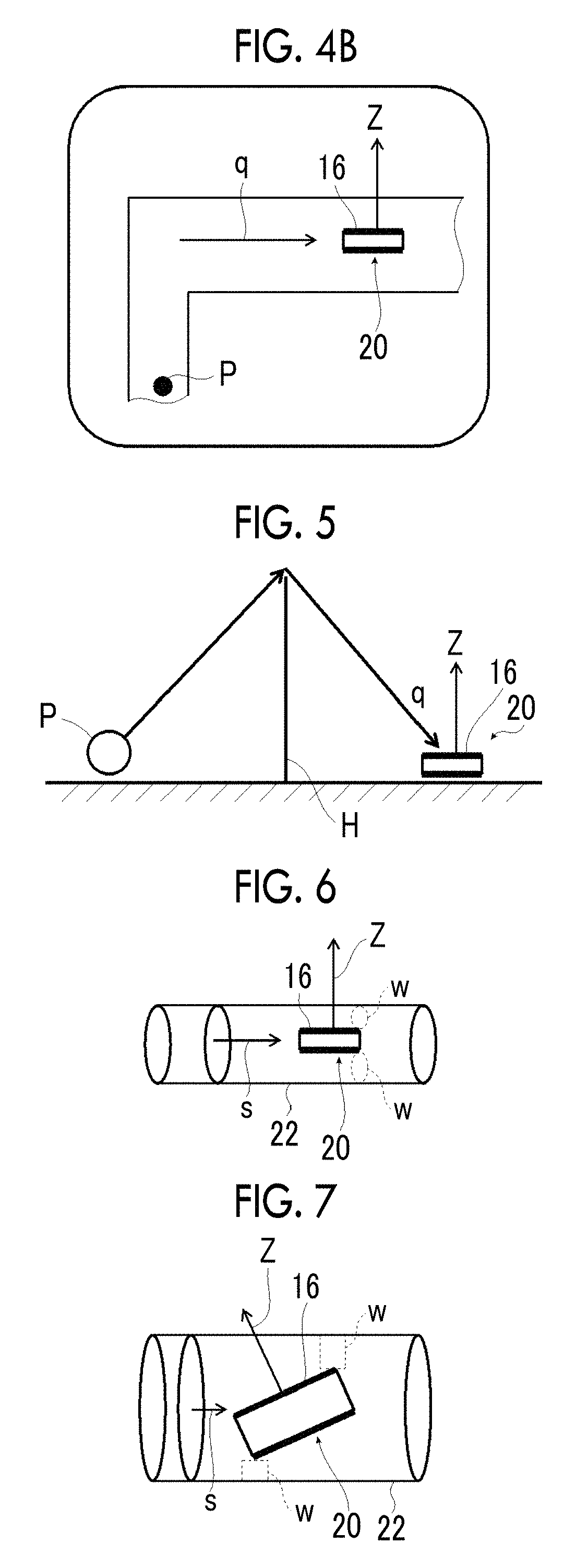
  • Soundproofing structure, opening structure, cylindrical structure, window member, and partition member
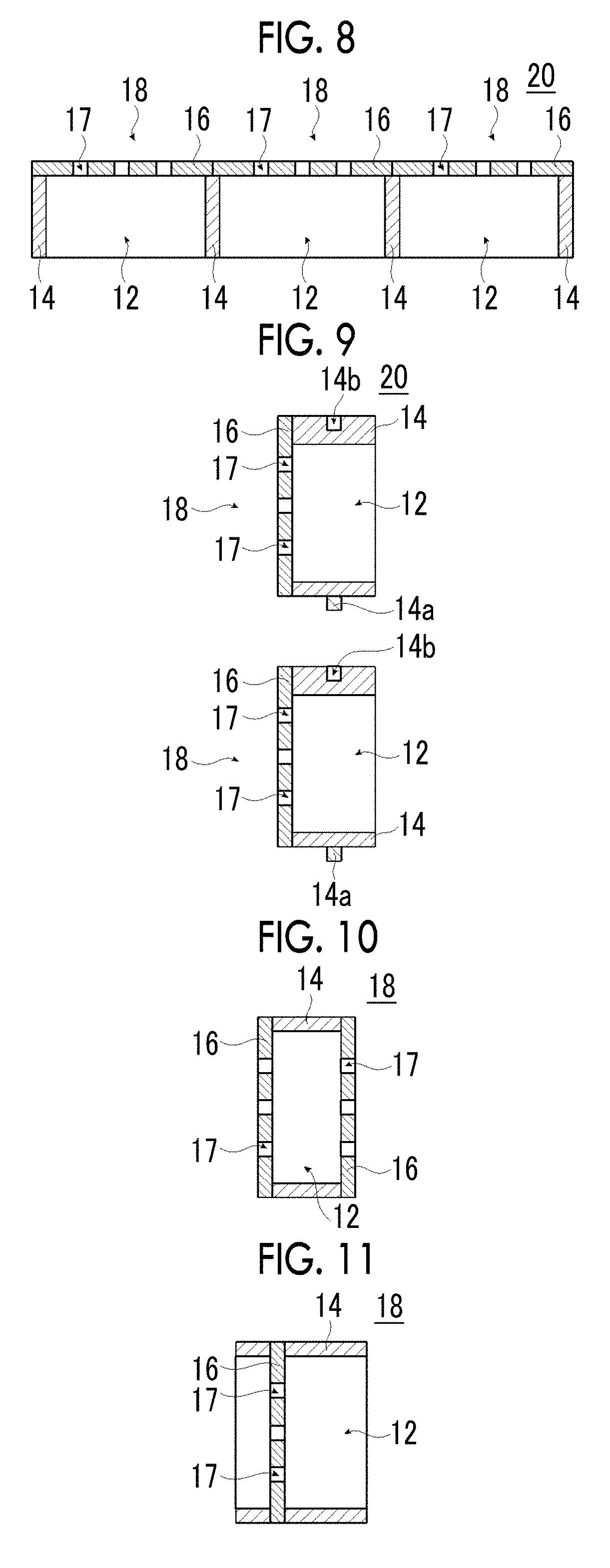
  • Soundproofing structure, opening structure, cylindrical structure, window member, and partition member

Examples


example 1

[0468]

[0469]The treatments described below were performed on a surface of an aluminum substrate (JIS H-4160, alloy No.: 1N30-H, aluminum purity: 99.30%) having an average thickness of 20 μm and a size of 210 mm×297 mm (A4 size), thereby preparing a film 16 having a plurality of the through-holes 17.

[0470](a1) Aluminum Hydroxide Film Forming Treatment (Film Forming Step)

[0471]The aluminum substrate was used as a cathode, and an electrolytic treatment was performed thereon for 20 seconds under a condition of a total electric quantity of 1000 C / dm2 using an electrolytic solution (nitric acid concentration of 10 g / L, sulfuric acid concentration of 6 g / L, aluminum concentration of 4.5 g / L, flow rate of 0.3 m / s) whose temperature was kept to 50° C. to form an aluminum hydroxide film on the aluminum substrate. Further, the electrolytic treatment was performed using a DC power supply. The current density was 50 A / dm2.

[0472]After formation of the aluminum hydroxide film, the film was washed ...

examples 5 to 10

[0503]Each film having through-holes with an average opening diameter of 15 μm and an average opening ratio of 3.7% was prepared by changing the conditions for preparing the film, and the film was fixed to a frame, thereby preparing a soundproofing cell B.

[0504]One to six soundproofing cells B were respectively fixed in series to prepare a soundproofing structure.

[0505]The absorbance of each of the prepared soundproofing structures was measured in the same manner as in Example 1. The measurement results of Examples 5, 7, and 10 are shown in FIG. 21. Further, the results obtained by measuring the average opening diameters, the average opening ratios, the number of soundproofing cells, and the absorbances at a frequency of 4000 Hz of each example are listed in Table 2.

[0506]

TABLE 2AverageopeningAverageAbsorbancediameteropeningNumber of(%)μmratio %soundproofing cells@ 4000 HzExample 5153.7148.9Example 6153.7274.7Example 7153.7384.2Example 8153.7494.3Example 9153.7597.1Example 10153.769...

examples 11 and 12

[0509]Soundproofing structures were prepared respectively in the same manners as in Example 7 and 10 except that the height of the frame was changed to 10 mm.

[0510]The absorbance of each of the prepared soundproofing structures was measured in the same manner as in Example 1. Further, the results obtained by measuring the average opening diameters, the average opening ratios, the number of soundproofing cells, the heights of the frames, and the absorbances at a frequency of 4000 Hz of Examples 7 and 10 to 12 are listed in Table 3.

[0511]

TABLE 3AverageHeightopeningAverageNumber ofofAbsorbancediameteropeningsoundproofing frame(%)μmratio %cellsmm@ 4000 HzExample 7153.732084.2Example153.762098.410Example153.731020.411Example153.761038.812

[0512]As shown in Table 3, it was found that the absorbance is increased as the height of the frame is increased. In other words, it was found that the through-holes formed in the film and the height of the frame contribute to the sound absorption effect...


PUM

PropertyMeasurementUnit
opening diameteraaaaaaaaaa
surface roughnessaaaaaaaaaa
average particle diameteraaaaaaaaaa

Abstract

An object is to provide a soundproofing structure which exhibits high soundproofing performance in a broad frequency band, can be miniaturized, can ensure ventilation properties, and has a light transmittance, and a cylindrical structure, a window member, and a partition member including this soundproofing structure. Provided is a soundproofing structure including: a soundproofing cell which includes a frame having a frame hole portion passing therethrough and a film that covers the frame hole portion and is fixed to the frame, in which the film has a plurality of through-holes passing therethrough in a thickness direction, an average opening diameter of the through-holes is in a range of 0.1 μm to 250 μm, and a vertical direction of a film surface is disposed so as to be inclined with respect to a direction of a sound source to be soundproofed.

Description

CROSS-REFERENCE TO RELATED APPLICATIONS[0001]This application is a Continuation of PCT International Application No. PCT / JP2017 / 012267 filed on Mar. 27, 2017, which claims priority under 35 U.S.C § 119(a) to Japanese Patent Application No. 2016-066246 filed on Mar. 29, 2016 and Japanese Patent Application No. 2016-090510 filed on Apr. 28, 2016. Each of the above application(s) is hereby expressly incorporated by reference, in its entirety, into the present application.BACKGROUND OF THE INVENTION1. Field of the Invention[0002]The present invention relates to a soundproofing structure, and an opening structure, a cylindrical structure, a window member, and a partition member having the soundproofing structure.2. Description of the Related Art[0003]In many cases, typical noise is over frequencies in a broadband, a low frequency sound is felt as a pressure, a sound in a mid range (approximately 1000 Hz to 4000 Hz) is felt loud since the structure of an ear is formed to be sensitive to t...

Claims


Application Information

Patent Timeline
Patent Type & Authority Patents(United States)
IPC IPC(8): E04B1/84G10K11/16E04B1/99G10K11/172G10K11/162B32B1/00E04B2/74
CPCG10K11/162E04B1/84G10K11/16G10K11/161G10K11/172E04B2001/8433B32B1/00E04B1/99E04B2/7409E04B2/7416
Inventor HAKUTA, SHINYAYAMAZOE, SHOGOKOMATSU, HIROSHI
Owner FUJIFILM CORP
Learn More