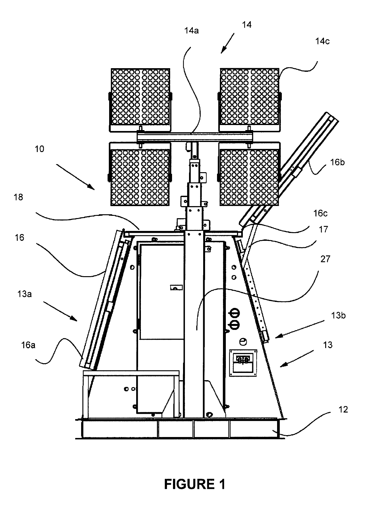
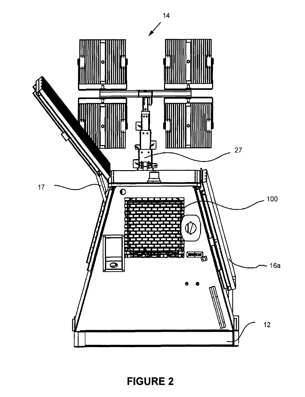
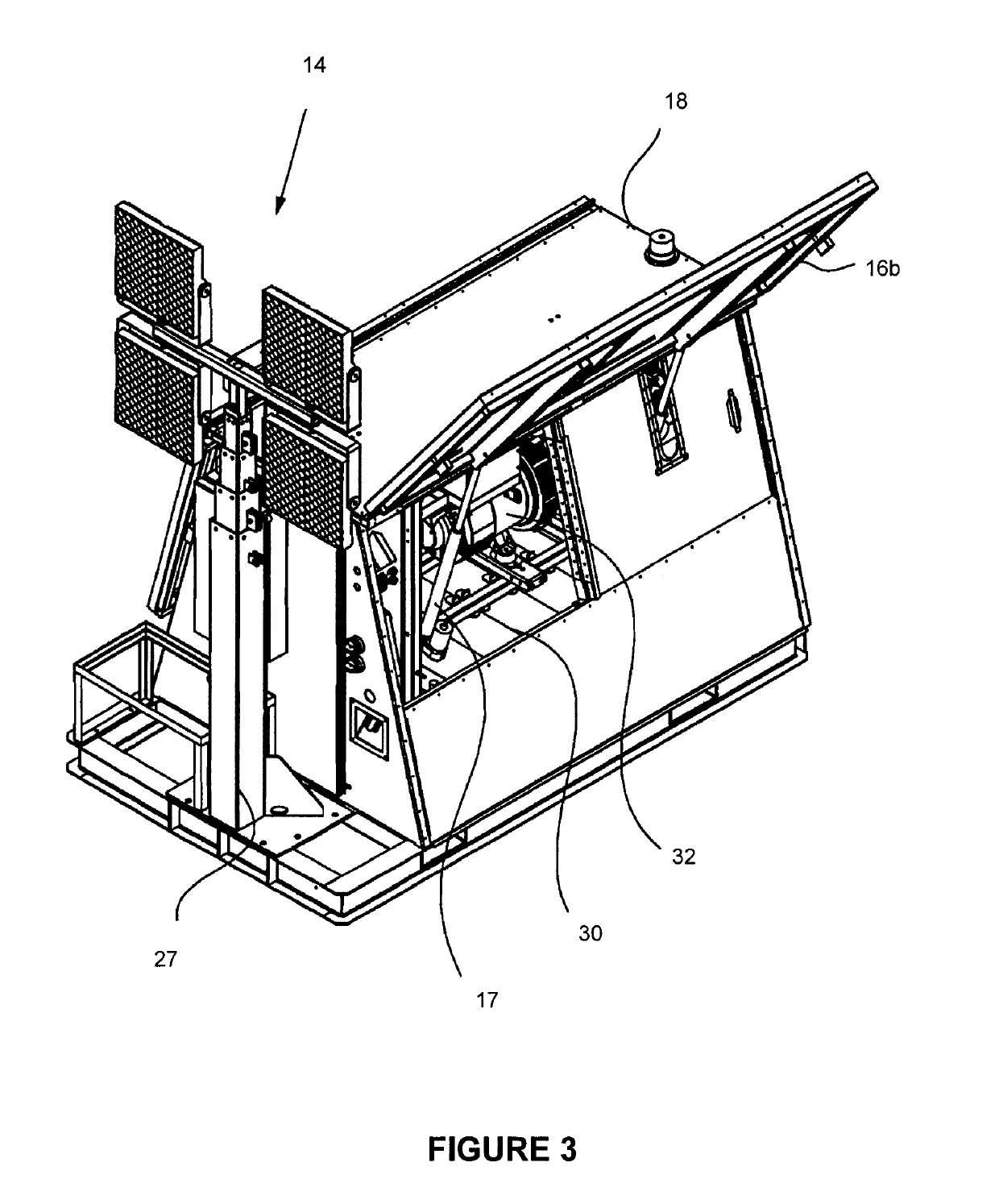
That is, delivering fuel to a remote location substantially increases the cost of fuel often by several multiples as compared to deployment of the same equipment in a non-remote setting.
As can be appreciated, the increase in delivery costs is due to increased equipment and personnel costs required to transport and deliver fuel to locations where it takes time and specialized equipment to get it to the remote location.
Similarly, reliability of the supply chain to various locations such as military zones, remote drilling sites and mines can result in direct and indirect costs resulting from the inability and / or time to physically deliver fuel to a location to run equipment at the site.
As is known, in addition to the increased costs associated with operating equipment at a remote location, there are several other drawbacks with these lighting systems.
These include:noisy operation at night;high fuel consumption;inability to operate due to fuel shortages or delays;
impact of weather on refueling schedules in remote or
high latitude locations;
high carbon footprint;toxic emissions;no controller, instead having switches, toggles and buttons;engine service requirements particularly resulting from the high run time hours and / or operation in cold climates;increased maintenance costs due to operation in a remote location;inefficient operation particularly during
cold weather where ICEs may need to be run during
daylight hours to maintain ICE warmth to ensure nighttime reliability; andhigh personnel costs due to the complexity of system set-up and the time required for manual operation and / or operator supervision.
However, while some localized savings can be achieved by systems incorporating secondary power sources, the efficiency and / or reliability of these secondary sources of power can simply create other operational problems.
Moreover, on a practical scale such systems are generally unable to provide sufficient power to power
metal halide light bulbs that are commonly used in traditional ICE powered mobile lighting systems.
However, while LED's reduce energy draw, the operator will typically only realize an approximate 30-40% reduction in fuel cost if LED lights are simply installed on a standard light
tower in place of
metal halide bulbs because ICE operation remains inefficient relative to the energy requirements of the bulbs and with respect to the overall management of energy at a remote site.
That is, the savings in fuel are not linear to the power reduction resulting from the use of the LEDs.
Unfortunately there are number of drawbacks with these systems that make these systems unreliable or unusable in a number of operational situations, and particularly in remote, harsh and cold climates.
Similarly, at higher latitudes, at times of the year with short days (i.e. winter), there is not enough time during the day to generate energy (at a reasonable cost and
footprint) using solar powered lighting systems for the correspondingly longer nights when the energy is drawn as well as there being limits on the maximum energy that can be stored in an economically sized
battery bank.
Further still, because these are mobile lighting systems that must be transported to remote sites, often along very rough roads, there are size restrictions for all components that do not enable operators to simply increase the size of
renewable energy collection equipment.
That is, there is limited surface area available on the structure for solar panels which thereby limits the amount of
solar power that can be collected in a given time period.
As such, solar systems are generally not suitable for climates where the ratio of light power generating hours to night-time energy drawing hours is not favorable or where during certain times of the year such as a rainy season there is limited good quality
solar light.
Similarly, the reliability of
wind power in many locations is not sufficient to enable the long term use of this
energy source.
Furthermore, with regards to
solar power, local weather conditions may not be favorable for considerable time periods, as there may be considerable
cloud cover and / or
precipitation at times. In cold climates, large amounts of
snow may accumulate on the surface of the solar panels, preventing or reducing the amount of sun's rays that reach the solar panel.
Geographic features at a particular location may also not be favorable.
As drilling equipment will typically be moved from site to site in these remote locations, the operator will often have to choose between incurring higher costs to purchase both an ICE system and a
solar system (to have the ability to utilize solar when available but have the ICE as a reliable
backup) or have a single ICE system reliable in all operations (but then have no ability to capture renewable power when available).
However, current solar systems have no ability to provide power for the operation of ancillary equipment.
That is, even during long sunny summer days, due in part to the limited available space for solar panels on a mobile system, a light
tower may only be able to absorb enough energy on a given day to supply the lighting for that night thus leaving little to no extra energy to power ancillary equipment.
Thus, as light towers traditionally have the
dual purpose of supplying power to the lighting fixture as well as supplying power and / or
backup power to ancillary equipment, a significant drawback of solar and wind powered light towers is that they are limited to only lighting and only in certain geographic locations and only in certain environmental conditions.
This drawback eliminates the ability of an operator to reduce their
carbon footprint, because in order to do so they would have to sacrifice functionality.
As noted above, specifically in harsh, remote and / or cold environments, solar and / or wind systems have not been capable of reliably supplying lighting systems for these environments.
Further still, in the harsh environment of northern latitudes (e.g. northern Canada or Alaska), particularly during the
winter season with reduced
daylight hours, another operational issue is that such systems are often affected by reduced battery performance due to the cold,
snow cover of solar panels and / or the risk of
moving parts of a wind
turbine (for example) becoming frozen.
Use of stored power for heating devices within the system that may allow such systems to operate reliably in cold climates will almost always exceed the available power from renewable sources alone.
While an operator may wish to reduce their
carbon footprint, the cost of doing so in a meaningful way is generally prohibitive.
As such, wind turbines are generally not easily transportable, and they can be difficult and time-consuming to set-up and take down.
An operator often has to perform many time-consuming steps to set up and take down a wind
turbine.
Harsh weather conditions including strong winds, cold temperatures and rain / snowfall, can make it more difficult and dangerous to
handle and manipulate a wind
turbine.
As diesel engines heat a fuel / air mixture by compression, it becomes increasingly difficult to achieve ignition temperature as ambient temperatures fall.
Furthermore, diesel fuels often gel at cold temperatures, and lubricating oils become more viscous and can impede rather than lubricate
moving parts.
As such, ICE systems can become virtually unstartable when temperatures fall much below freezing, which is why they are often kept idling continuously in
cold weather.
As can be appreciated, continuously idling an engine is not fuel-efficient as it continually requires fuel, resulting in a higher
carbon footprint and increased toxic emissions, as well as increased sound
pollution.
Cold temperatures can also adversely affect battery banks by decreasing the time period a battery can hold its charge and shortening the lifespan of the batteries.
This is important to note because when solar may already be limited due to solar panel
footprint or environmental conditions, losses in the overall systems due to the cold effect on batteries (or other losses such as line losses, etc.) can void the benefit gained by solar input.
As such, manpower is required for the operation of the prior art systems in a way that is bulky, inefficient and leaves room for
human error that can result in system failures.
A review of the prior art indicates that past systems have been developed that provide particular functions but that do not provide systems enabling effective operation in remote, higher
latitude and / or harsher climates.


