Dot projector with automatic power control

a projector and power control technology, applied in the direction of semiconductor lasers, laser details, electrical apparatus, etc., can solve the problems of large device volume, inability to apply surface mount technology, and inability to apply technology in applications, etc., to achieve stable emitted light, simple integration, and light volume

Active Publication Date: 2019-09-17
ARIMA LASERS CORP
View PDF1 Cites 9 Cited by
  • Summary
  • Abstract
  • Description
  • Claims
  • Application Information

AI Technical Summary

Benefits of technology

[0018]In short, the substrate integrates the automatic power control IC of the photodiode, the mounting seat, the laser diode, the reflector, the housing, the collimator and the DOE within the emitter device, and the laser diode, the automatic power control IC and the reflector forms a feedback control structure of the laser light which is further stably emitted by the control and temperature compensation of the automatic power control IC. The present invention therefore has features of simple integration, light volume, low prime costs and stable output of the laser light and the laser light spots.

Problems solved by technology

Also, when a laser diode is activated, even minor changes of voltages can lead to a dramatic change of the electric currents.
However, such device has a huge volume and cannot be integrated in applications; on the other hand, such technology cannot be applied to surface mount technology either.
However, such device has a huge volume and complicated assembly structure, and the radiation source assembly 21 cannot be applied to surface mount technology either, making it impossible for automatic manufacturing process.
Even if replacing the radiation source assembly 21 of the dot projector 20 by the laser diode module 10, the problems of huge volume and complicated structure are still exiting, or the problems could be worse.

Method used


Image

  • Dot projector with automatic power control
  • Dot projector with automatic power control
  • Dot projector with automatic power control

Examples


Embodiment Construction

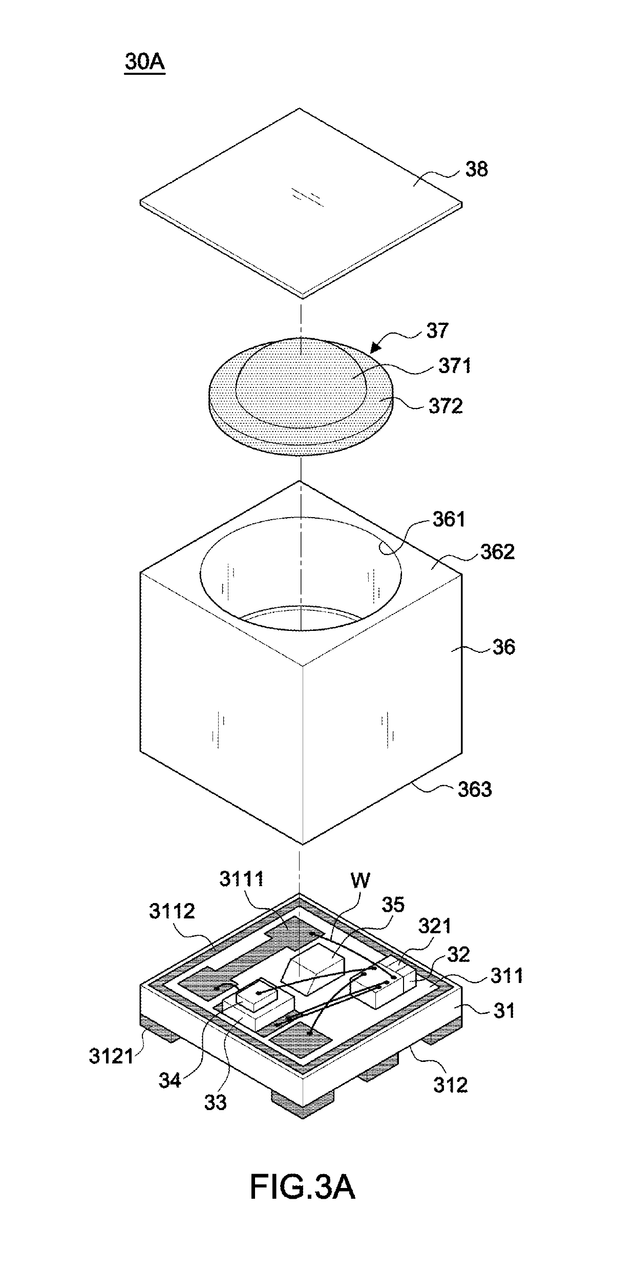
[0030]Referring to FIGS. 3A-3C and 5-7, in a preferred embodiment, a dot projector with automatic power control 30A mainly includes a substrate 31, an automatic power control integrated circuit (IC) 32, a mounting seat 33, a laser diode 34, a reflector 35, a housing 36, a collimator 37 and a diffractive optical element (DOE) 38.

[0031]The substrate 31 includes a first surface 311 with a first conductive pad 3111 and a second surface 312 with a second conductive pad 3121 in this embodiment. The first and second surfaces 311, 312 are arranged at opposite sides correspondingly and the substrate 31 is made of a printed circuit board for an internal wire to be coupled with the first and second conductive pads 3111, 3121; the second conductive pad 3121 is connected to an external circuit O, but the present invention is not limited to such application.

[0032]The automatic power control IC 32 is mounted on the substrate 31 and includes a photodiode 321 connected to the automatic power control...


PUM


Abstract

A dot projector with automatic power control includes a housing covering a substrate with an installing space and a platform therein, an automatic power control integrated circuit, a photodiode and a reflector disposed under the platform of the housing, a collimator disposed in the installing space of the housing and a diffractive optical element bonded on the platform of the housing. Whereby a laser diode emits a laser light to the reflector for the laser light to be reflected perpendicularly through the collimator to the diffractive optical element; then the diffractive optical element produces a plurality of light spots and the a stray light is also produced from the laser light. The photodiode of the automatic power control integrated circuit then detects the stray light and produces a feedback signal transmitted back to the laser diode for adjustment of the laser emission power in order to control the light spots produced by the diffractive optical element.

Description

BACKGROUND OF THE INVENTION1. Field of the Invention[0001]The invention relates to a dot projector, particularly to one that has a feedback signal of stray light transmitted back for a photodiode of an automatic power control integrated circuit to detect and thereby adjust power of a laser light emitted by a laser diode to control light spots produced by a diffractive optical element of the emitter.2. Description of the Related Art[0002]The luminous intensity of laser diodes can be affected by the amount of driving currents and temperature. The higher the driving currents are, the greater the luminous intensity is, and the higher the temperature is, the greater the optical attenuation is. Also, when a laser diode is activated, even minor changes of voltages can lead to a dramatic change of the electric currents. Therefore, automatic power control is necessary for laser diodes to hold control of the laser lights emitted. FIG. 1 is a laser diode module 10 disclosed in U.S. Pat. No. 7,...

Claims


Application Information

Patent Timeline
Patent Type & Authority Patents(United States)
IPC IPC(8): H01S5/02H01S5/068H01S5/022
CPCH01S5/06808H01S5/02292H01S5/02296H01S5/02212H01S5/02288H01S5/005H01S5/0071H01S5/02208H01S5/06825H01S5/0683H01S5/02257H01S5/02325H01S5/02345H01S5/02253H01S5/02255
Inventor HWANG, JUNG-MINHSIEH, CHIA-HUNGLIN, CHUN-TINGWU, MING-CHOFANG, MING-HUI
Owner ARIMA LASERS CORP
Why Eureka
Try Eureka