

Thermally insulated components for exhaust systems
a technology of exhaust system and components, applied in the direction of inorganic insulation, machines/engines, mechanical equipment, etc., can solve the problems of relatively high cost of heat shields, high installation or replacement costs, etc., and achieve the effect of improving/lowing the emissions of products and low cos
- Summary
- Abstract
- Description
- Claims
- Application Information
AI Technical Summary
Benefits of technology
Problems solved by technology
Method used
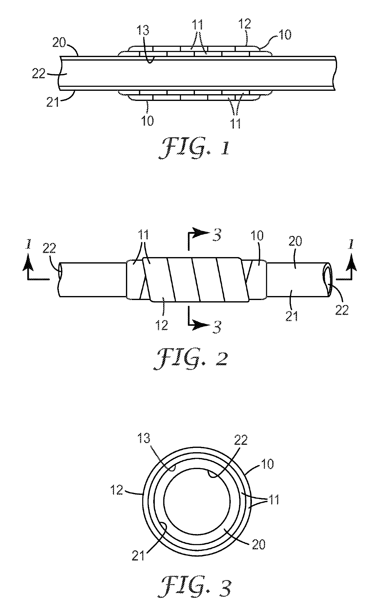
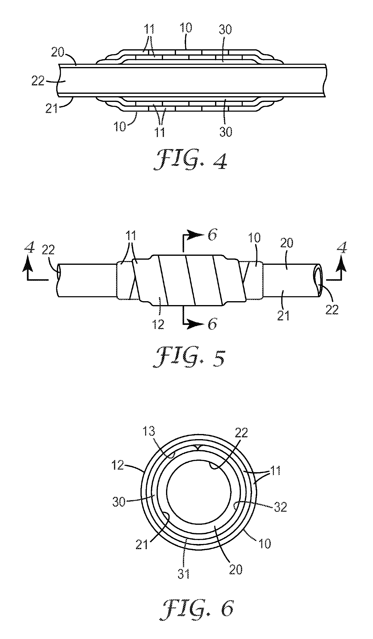
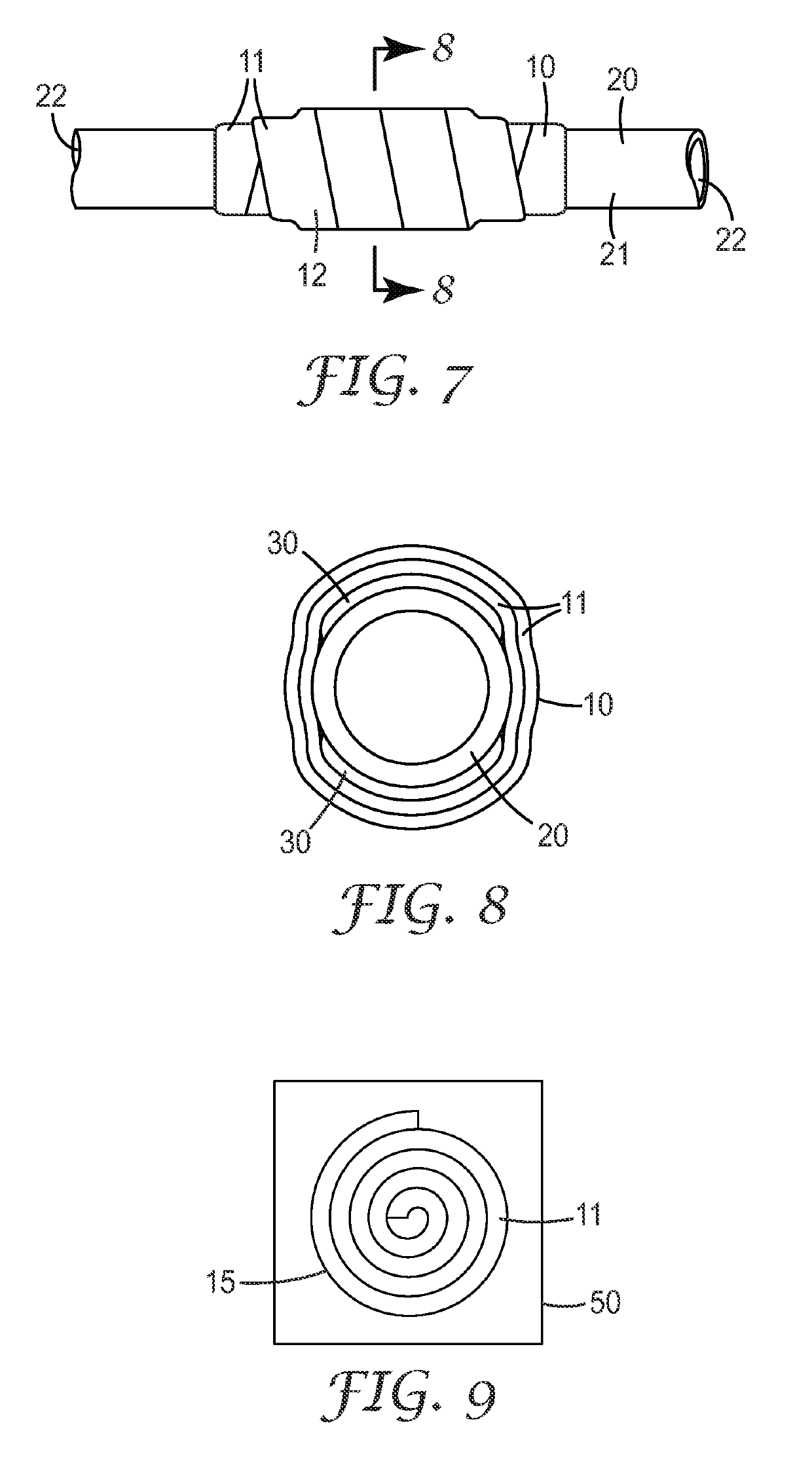
Image

Examples
example 1
[0077]Embodiments of the invention were produced by the method generally described herein.
[0078]Slurries were prepared using ingredients shown above. In each slurry, inorganic materials were added to liquid component(s) using a high shear mixer and blended until smooth to form a given slurry as shown in Table 2 below.
[0079]
TABLE 2SlurriesSlurryComposition150 wt % 2327 colloidal silica, 50 wt % POLYPLATE ™ P267 wt % 2327 colloidal silica, 33 wt % calcium carbonate357.1 wt % 1144 colloidal silica, 42.9 wt % calcium carbonate494.4 wt % 2327 colloidal silica, 5.6 wt % M-5 fumed silica587.8 wt % 1144 colloidal silica, 12.2 wt % M-5 fumed silica660 wt % 2327 colloidal silica, 40 wt % talc752.9 wt % 1144 colloidal silica, 47.1 wt % talc860 wt % 2327 colloidal silica, 40 wt % silicon carbide950 wt % 2327 colloidal silica, 40 wt % aluminum powder,10 wt % POLYPLATE ™ P1082.3 wt % 2327 colloidal silica, 17.7 wt % bentonite clay1184 wt % 2327 colloidal silica, 16 wt % fumed alumina1284.4 wt % 2...
example 2
[0083]Additional test samples were prepared using the procedures of Example 1. The following test samples utilized various colloidal binders. Results are shown in Table 4.
[0084]
TABLE 4Test Samples and ResultsTestCoatedDryCrushSampleSlurryweight (g)weight (g)Conditionstrength N1002574.358901611012571.656.1500 3071022569.454.6500 wet225103266545.990871042659.542.7500 1841052660.332.2500 wet1541062765.654.2901361072760.850.6500 2701082761.751.3 500 Wet2121092875.658.9902171102874.358500 4201112871.656.1500 wet3601122983.152.890681132971.947500 1361142972.547.3500 wet911152471.750901731162469.148.5500 260117247049500 wet247118304931.690111193049.331.7500 18120305333.2500 wet181213153.3309013.51226287.766.490961236280.561.8500 1871246280.862.3500 wet1411256478.558902111266470.853500 3781276467.751500 wet33112867786090198129677256500 468130677357500 wet42813168735690122132686752500 227133686853500 wet17713469755690112135696549500 211136696650500 wet13713770725490253138706953500 3611397071...
example 3
[0085]Additional test samples were prepared using the procedures of Example 1. The following test samples utilized sodium silicate binders. Results are shown in Table 5.
[0086]
TABLE 5Test Samples and ResultsTestCoatedDryCrushSampleSlurryweight (g)weight (g)Conditionstrength N2003680.243.6902082014093.955.3903132024181.954902022034183.754500 2422044185.656500 wet2402054270.3647.2903832064269.846.9500 1312074267.7745.8500 wet1502084454.835.9902572094461.438.9500 902104463.139.7500 wet802114566.341.7902752124559.938.7500 1322134560.438.9500 wet942144668.143.9901452154660.339.5500 1752164659.739.2500 wet1532175171.845.590832185159.639.5500 1292195245.5219032205245.521500 22215245.521500 wet22225347.622.790132235344.522.4500 122245345.5122.5500 wet72255448.625.69026226544725.3500 262275446.525.2500 wet26
PUM
| Property | Measurement | Unit |
|---|---|---|
| size | aaaaa | aaaaa |
| surface temperature | aaaaa | aaaaa |
| surface temperature | aaaaa | aaaaa |
Abstract
Description
Claims
Application Information