Motor driving device

a technology for driving devices and motors, applied in the direction of electric motor control, vehicle heating/cooling devices, transportation and packaging, etc., can solve problems such as motor noise, and achieve the effect of smooth motor rotation

Active Publication Date: 2020-02-25
DENSO CORP
View PDF10 Cites 0 Cited by
  • Summary
  • Abstract
  • Description
  • Claims
  • Application Information

AI Technical Summary

Benefits of technology

The process of selecting one signal by avoiding the overlap of frequencies from a plurality of signals is possible by changing the program of the control unit. Therefore, according to the motor driving device, it is possible to sequentially change the carrier frequency of the PWM without requiring the modification of the existing circuit.
The process of randomly selecting one signal from a plurality of signals is possible by changing the program of the control unit. Therefore, according to the motor driving device, it is possible to sequentially change the carrier frequency of the PWM without requiring the modification of the existing circuit.
According to the motor driving device, even when the effective value of the voltage applied to the motor changes due to the change in the carrier frequency of the PWM, the same voltage as the PWM due to the reference frequency can be applied to the motor, and thus the rotation of the motor can be controlled smoothly.
According to the motor driving device, even when the effective value of the voltage applied to the motor changes when the carrier frequency of the PWM changed due to the influence of the dead time, the same voltage as the PWM due to the reference frequency can be applied to the motor, and thus the rotation of the motor can be controlled smoothly.
In addition, the motor driving device includes a rotation speed detection unit that detects a rotation speed of the motor, and the control unit calculates a driving voltage of the motor so as to eliminate a deviation between a target rotation speed indicated by the command signal and an actual rotation speed of the motor detected by the rotation speed detection unit.
According to the motor driving device, the driving voltage is calculated by a proportional-integral (PI) controller that eliminates the deviation between the rotation speed indicated by the command signal and the actual rotation speed of the motor, and thus it is possible to control the rotation speed of the motor in consideration of the actual rotation speed of the motor.

Problems solved by technology

However, noise may be generated from the motor according to the PWM control.

Method used


Image

  • Motor driving device
  • Motor driving device
  • Motor driving device

Examples


first embodiment

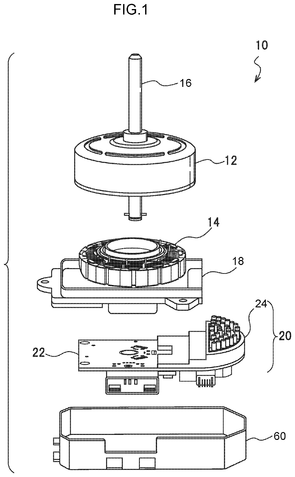
FIG. 1 is a schematic diagram showing a configuration of a motor unit 10 using a motor driving device 20 according to the present embodiment. The motor unit 10 of FIG. 1 according to the present embodiment is a unit of a so-called blower motor used for blowing air in an in-vehicle air conditioner as an example.

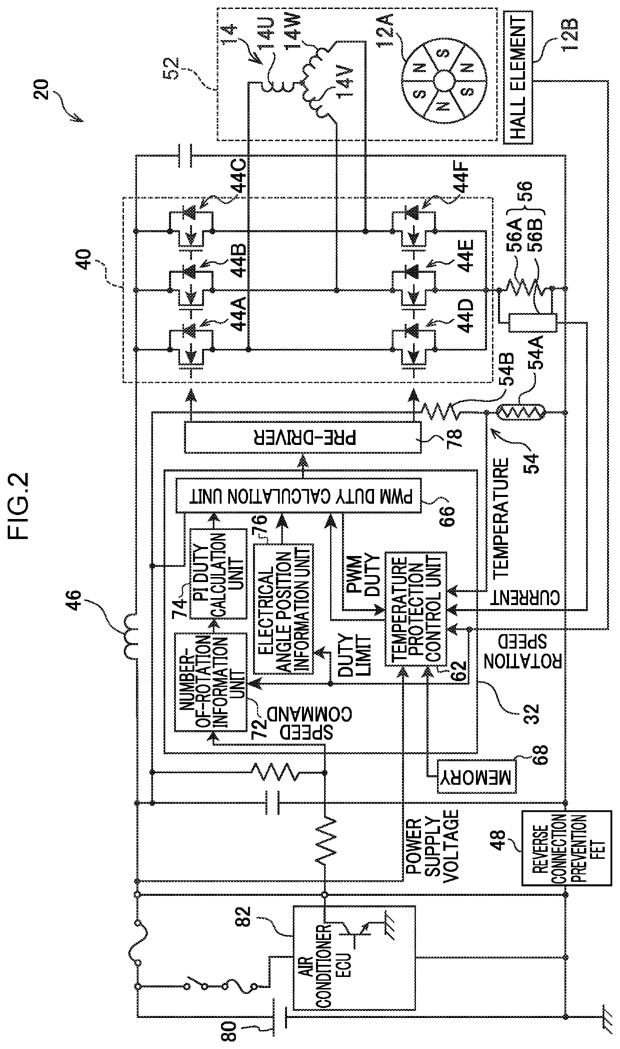
The motor unit 10 according to the present embodiment relates to a three-phase motor of an outer rotor structure in which a rotor 12 is provided outside a stator 14. The stator 14 is an electromagnet in which a conductive wire is wound around a core member, and constitutes three phases of a U-phase, a V-phase, and a W-phase. Each of the U-phase, the V-phase, and the W-phase of the stator 14 generates a so-called rotating magnetic field by switching the polarity of the magnetic field generated by the electromagnet under the control of the motor driving device 20 described later.

A rotor magnet is provided on the inner side (not shown) of the rotor 12, and the rotor magnet rotate...

second embodiment

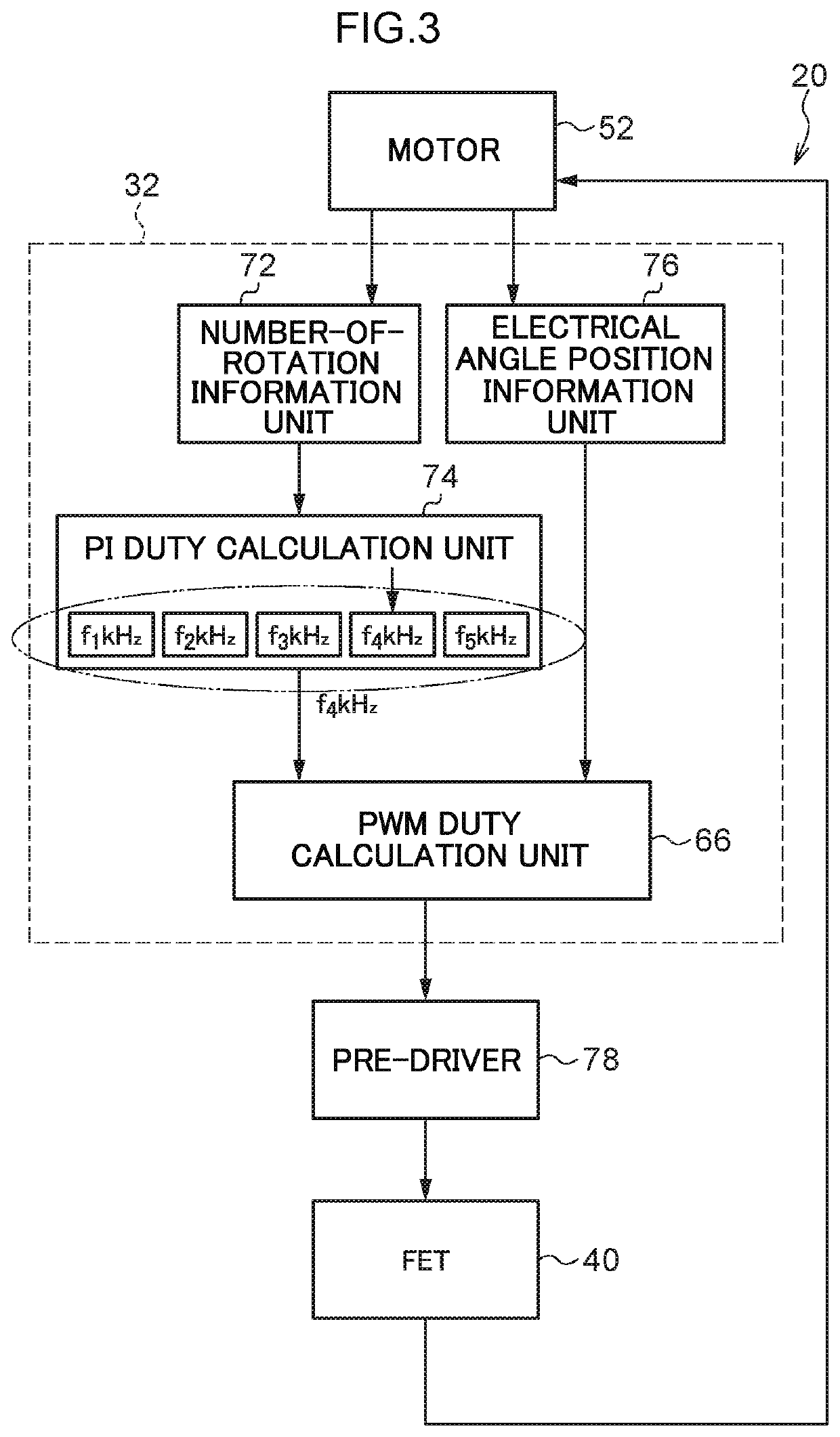
A second embodiment will be described below. In the first embodiment, the noise generated from the motor 52 is reduced by changing the carrier frequency related to the generation of the PWM signal for each control period of the microcomputer 32. However, when the carrier frequency related to the generation of the PWM signal is changed, the duty ratio of the voltage applied to the motor 52 may change and noise may be generated from the motor 52. In order to suppress such noise, for example, one reference frequency is determined from f1 kHz, f2 kHz, f3 kHz, f4 kHz, and f5 kHz, and the voltage generated based on the PWM signal according to the frequency other than the reference frequency is made equal to the voltage generated based on the PWM signal of the period according to the reference frequency.

In the microcomputer for the motor control, like the inverter FET 44A and the inverter FET 44D, in order to prevent a through-current from flowing through the FETs connected in series, a de...


PUM


Abstract

API duty calculation unit of a microcomputer that performs control at a predetermined control period calculates a duty ratio of a voltage applied to a coil of a motor from a target rotation speed and an actual rotation speed calculated by a number-of-rotation information unit. The PI duty calculation unit generates a rectangular wave signal having a period according to one frequency selected from plural predetermined frequencies together with the start of one control period and indicating the calculated duty ratio, and outputs the rectangular wave signal to a PWM duty calculation unit. The PWM duty calculation unit generates a PWM signal for controlling an inverter circuit based on the rectangular wave signal output by the PI duty calculation unit and position information of a rotor of the motor calculated by an electrical angle position information unit.

Description

TECHNICAL FIELDThe present invention relates to a motor driving device.BACKGROUND ARTA control device of a brushless DC motor (hereinafter abbreviated as a “motor”) used for a blower motor or the like of a vehicle air conditioner causes an inverter circuit to generate a voltage having a duty ratio corresponding to a target rotation speed, and applies the generated voltage to a coil of the motor.An inverter circuit 40 includes a switching element. The inverter circuit 40 generates a voltage to be applied to the coil of the motor by a pulse width modulation (PWM) that adjusts a voltage by turning on and off the switching element to modulate a DC voltage of a power supply into a pulsed waveform. However, noise may be generated from the motor according to the PWM control.In order to suppress the noise caused by the PWM, spread spectrum that sequentially changes one cycle of the waveform of the voltage generated by the PWM is effective. In order to change one cycle of the waveform of the...

Claims


Application Information

Patent Timeline
Patent Type & Authority Patents(United States)
IPC IPC(8): H02P27/08B60H1/00H02P27/06H02P27/04
CPCB60H1/00428H02P27/06B60H1/00642H02P27/085H02P27/045Y02T10/88H02P27/08H02M7/5395H02P2209/00
Inventor OTSUKA, HIKARU
Owner DENSO CORP
Why Eureka
Try Eureka