Power module and method for manufacturing power module

a technology of power modules and power modules, applied in the direction of electrical apparatus, semiconductor devices, semiconductor/solid-state device details, etc., can solve the problems of low conformability and/or low thermal conductivity of most thermal interface solutions commercially available today, and achieve the effect of high conformability and high thermal conductivity

Active Publication Date: 2020-04-14
MITSUBISHI ELECTRIC CORP
View PDF8 Cites 2 Cited by
  • Summary
  • Abstract
  • Description
  • Claims
  • Application Information

AI Technical Summary

Benefits of technology

[0006]The invention aims at providing a highly-conformable, highly thermally conductive, isolating and low-cost interface between a substrate, such as a PCB, and a heat-sink.
[0017]Thus, no air is blocked in the first cavity of the second material during the manufacturing process, and both dielectric isolation and thermal conductivity are guaranteed.
[0019]Thus, the first material is very soft, highly conformable, and easily dispensable, and the second and third materials are low-cost, isolating, and ensure a defined distance between the substrate and the heatsink. In addition, the second and the third material can be assembled with a standard PCB process. If the substrate is a PCB, the second and third materials can be assembled to the substrate in the same process step as the substrate.
[0029]Thus, the first material can be dispensed in the entire first cavity with a simple low-cost and reliable process.

Problems solved by technology

Most thermal interface solutions commercially available today exhibit either low conformability and / or low thermal conductivity like for example FR4 pre-preg, polymide and / or no / low electric isolation like for example thermal grease, graphite pads, and / or high cost like for example isolating pads.

Method used


Image

  • Power module and method for manufacturing power module
  • Power module and method for manufacturing power module
  • Power module and method for manufacturing power module

Examples


Embodiment Construction

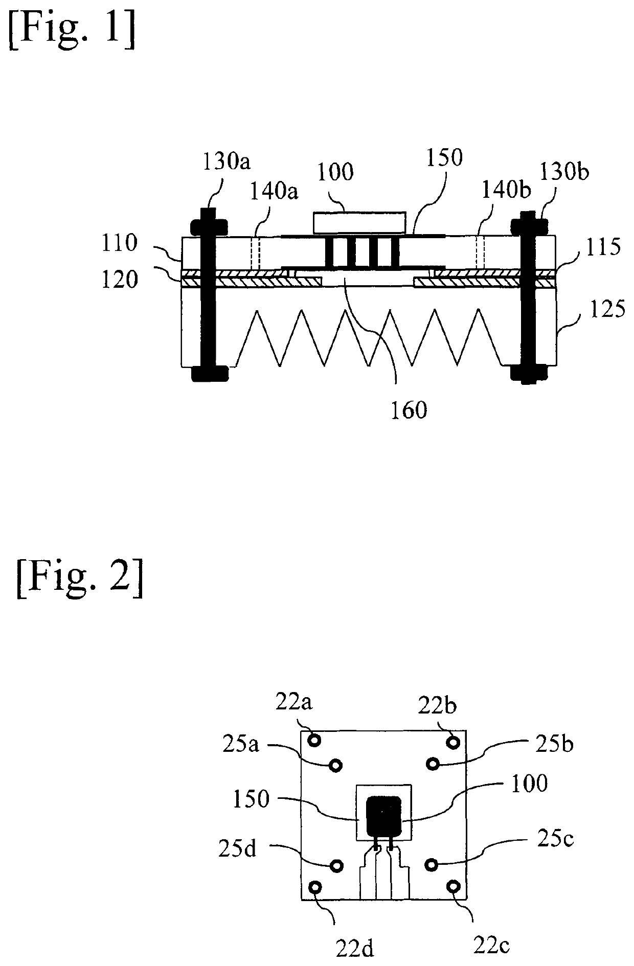
[0039]FIG. 1 is a diagram representing a first example of a section of a power module that uses a thermal interface assembly according to the invention.

[0040]The power module comprises a substrate 110 on which a power die 100 is attached (e.g. soldering). The substrate 110 is composed of two layers and thermal vias 150 that are filled with a thermally conductive material and capped so that solder does not flow through the via. Alternatively, copper inlay can be used.

[0041]In a variant, the power die 100 may be embedded in the substrate in the place of the thermal vias.

[0042]The substrate 110 may be also a multi-layer PCB wherein internal copper planes can be used to spread the heat towards the heat-sink 125. The substrate may contain some holes or un-filled vias 140a and 140b to allow gas circulation and gel drying / curing.

[0043]The power die 100 is a MOSFET, or an IGBT or a diode, in a SMD package such as DPak or D2Pak. Alternatively, the power die is embedded within the PCB.

[0044]T...


PUM


Abstract

The present invention concerns a power module comprising a heat sink, a substrate on which a power die is attached, the power module further comprises between the substrate and the heat sink, a first and a second materials, the first material having a thermal conductivity that is higher than the thermal conductivity of the second material, the second material having a first cavity below the power die and the first material is in the first cavity of the second material.

Description

TECHNICAL FIELD[0001]The present invention relates generally to a power module comprising a heat sink and a substrate on which a power die is attached.BACKGROUND ART[0002]Market penetration of wide band gap devices tends to promote low-inductance Surface Mounted Device (SMD) packages where heat extraction is realized through the Printed Circuit Board (PCB). It also tends to promote new packaging technologies where the power semiconductor dies are embedded within the PCB. These two trends allow not only fast switching cell, but also low-cost assembly.[0003]The thermal resistance of the PCB can be sufficiently reduced with thermal vias or thick metal inlays. The main bottleneck is presently on the thermal interface between PCB and heat-sink, that requires: a high conformability to compensate the large irregularities of the PCB and for bending effects due to unequal pressure application and thermo-mechanical strain, a high thermal conductivity to improve the cooling efficiency, an elec...

Claims


Application Information

Patent Timeline
Patent Type & Authority Patents(United States)
IPC IPC(8): H01L23/42H01L23/373H01L23/367H01L21/48
CPCH01L23/3735H01L23/3677H01L23/42H01L21/4882
Inventor DEGRENNE, NICOLAS
Owner MITSUBISHI ELECTRIC CORP
Why Eureka
Try Eureka