Inverter branch driver

a technology of inverter branch and driver, which is applied in the direction of logic circuits characterised by logic functions, ac-dc conversion, electrical apparatus, etc., can solve the problems of limited maximum functioning frequency of inverter, voluminous galvanic insulation, and inability to directly integrate control electronics to the inverter branch. , to achieve the effect of convenient integration

Active Publication Date: 2020-05-12
COMMISSARIAT A LENERGIE ATOMIQUE ET AUX ENERGIES ALTERNATIVES
View PDF13 Cites 0 Cited by
  • Summary
  • Abstract
  • Description
  • Claims
  • Application Information

AI Technical Summary

Benefits of technology

[0028]According to the invention and particularly advantageously, the use of synchronous input signals makes it possible to have an identical time reference for the first and second drivers. The use of phased input signals furthermore makes it possible to temporally offset these signals directly at the level of the first and second drivers. The first and second pluralities of logic gates subsequently make it possible to generate the first and second command signals having a very specific relative time difference. This offset is not due to external or prior control electronics, and can thus be precisely controlled by the first and second drivers. The use of one single and same input signal, duplicated so as to produce the first and second input signals, is also made possible by the invention. Thus, the invention makes it possible to significantly improve the precision over the time difference obtained and therefore to considerably increase the functioning frequency of the electronic circuit, for example, the switching frequency of an inverter.
[0050]Such an optocoupler also have a limited volume and can therefore be easily integrated in the same casing as the electronic circuit.

Problems solved by technology

In the case of an inverter branch, in particular based on a HEMT technology, such control electronics cannot be directly integrated to the inverter branch, due to the absence of transistors complementary to the HEMT having good performances (mobility of holes).
This galvanic insulation is also voluminous and difficult to integrate.
A disadvantage of this solution is that the maximum functioning frequency of the inverter is limited.
Another disadvantage of this solution is a limited immunity of the inverter facing a magnetic field, typically for a magnetic field of 10 Gauss to 1 MHz.
A disadvantage of this solution is that the maximum functioning frequency of the inverter is intrinsically limited.

Method used


Image

  • Inverter branch driver
  • Inverter branch driver
  • Inverter branch driver

Examples


Embodiment Construction

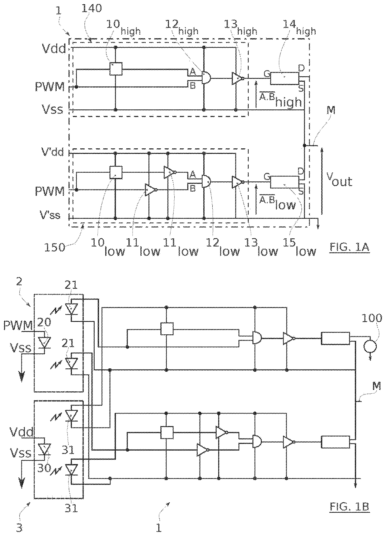
[0067]Before starting a detailed review of embodiments of the invention, it is reminded that the invention according to the first aspect thereof comprises, in particular, the optional features below, which could be used in association or alternatively:[0068]According to an embodiment, the gate transistors of the first and second pluralities of logic gates are only N-type channel field effect transistors.[0069]According to an embodiment, the first plurality of logic gates comprises at least:[0070]a first delay function logic gate configured to delay the first input signal, and[0071]a first AND-type logic gate comprising two inputs receiving respectively the first input signal and the first delayed input signal,[0072]and the second plurality of logic gates comprises at least:[0073]a second delay function logic gate configured to delay the second input signal, and[0074]a NO-type logic gate configured to invert the second delayed input signal, and another NO-type logic gate configured t...


PUM


Abstract

An electronic circuit is provided, including, on one same substrate, an inverter branch formed by high side and low side transistors, and the drivers of the high side and the low side transistors. The drivers include logic gates configured to receive one same PWM input signal and to generate two alternated command signals sent to the high side and the low side transistors. An inverter system is also provided, including the electronic circuit and laser optocouplers configured to electrically insulate the electronic circuit of a controller delivering a pulse width modulation (PWM) input signal and a main supply electrically supplying the drivers.

Description

TECHNICAL FIELD OF THE INVENTION[0001]The invention relates to command and control circuits for power converters. It has at least one particularly advantageous application in the field of inverters.STATE OF THE ART[0002]An inverter is a power converter, in particular used for converting a direct current (DC) into an alternating current (AC).[0003]Such an inverter generally comprises one or more inverter branches and one or more systems for driving the inverter branch.[0004]The inverter branch is formed by a high side switch, and a low side switch, alternatively functioning in half-bridge configuration so as to generate the AC current from the DC current.[0005]To convert a high power, it is advantageous to use power transistors to form high side and low side switches, for example GaN-based high electron mobility transistors (HEMT).[0006]The alternating controlling of these transistors is carried out by the command system.[0007]This command system generally comprises control electroni...

Claims


Application Information

Patent Timeline
Patent Type & Authority Patents(United States)
IPC IPC(8): H03K17/687H02M1/08H02M7/537H03K3/037H03K19/20
CPCH03K17/6871H02M7/537H03K3/037H02M1/08H03K19/20H03K2217/0063H03K2217/0072H01L27/02H02M7/48H03K17/51H03K17/78
Inventor BUCKLEY, JULIENESCOFFIER, RENE
Owner COMMISSARIAT A LENERGIE ATOMIQUE ET AUX ENERGIES ALTERNATIVES
Why Eureka
Try Eureka