Steerable biopsy needle

Active Publication Date: 2020-06-09
INTELLIGENT FIBER OPTIC SYST
View PDF10 Cites 1 Cited by
  • Summary
  • Abstract
  • Description
  • Claims
  • Application Information

AI Technical Summary

Benefits of technology

[0046]In one embodiment of the invention, the use of SMA materials for MR compatible guidance is also used to provide superelastic structures in outer stylet 126. The phase transition of SMA 124 may be used for actuation, but also in the outer stylet 126 to provide the flexibility needed to deflect the needle. SMA exhibits a so-called superelastic domain known as the austenite phase when the SMA temperature is sufficiently high. A stress increase can then induce a phase transition towards the martensite phase. This stress-induced phase transition is characterized by a large plateau in the stress-strain domain, providing increased deflection for a given applied force. In one embodiment of the present invention, this large elasticity domain is optionally used for the outer stylet 126 or stylet 132 of the active device. This approach allows the needle to achieve high deflections, due to device actuation or to interaction with tissues, and without plastic deformation.
[0047]In one embodiment of the invention as shown in FIGS. 1B, 1C, 1D, 1E, 1F, and 1G, the actuation mechanism is based on a laser machined SMA tube which forms the outer stylet 126 and SMA wire 124 which forms the active element attached to the outer stylet in first attachment extent 124 and second attachment extent 122. The flexible deflection extent 123 of the outer stylet 126 is formed from SMA tube and is 25 mm long, with a series of slits 160 with rounded ends 162 (to reduce stress concentrations) on one side or on both sides, as shown in FIGS. 1F and 1G. The rounded end 162 for reduction of stress concentration may take the form of a circular cut 162 joined with slit 160, with the bottom edge of the circle tangent to the neutral plane, shown as coincident with axis 121 of FIG. 1B. The number of slits 160 and the slit gap of 30 μm between two consecutive slits are chosen so that the 30 μm gap of each slit closes fully under maximum actuation. In this way, the device is always in a configuration for which the wire can generate a tension during its contraction, independent of the external interaction forces. Once the slits have closed (in the fully deflected position), the needle assembly becomes considerably stiffer with respect to additional bending loads. FIGS. 1E and 1G shows the anchor extent at one end of the outer stylet 126 which is created in one example shown by two holes 150 with the SMA wire 124 secured by threading the wire 124 through each hole 150. In an alternate embodiment, the SMA wire 124 anchoring is accomplished using a weld or other bond which minimizes stress concentrations at the anchor points of SMA wire 124 which could reduce the SMA wire life.
[0048]In addition to the SMA wire 124, which in a preferred embodiment is substantially 0.254 mm, the outer stylet 126 is formed from an SMA tube which is in close proximity to various optical fibers for SMA actuation through heating and sensing through stress induced in the SMA wire 124 from the actuation fibers 128,130. These elements, presented in the following section, are inserted in a flexible multi-lumen polytetrafluoroethylene (PTFE) tube which forms the body of stylet 132 to obtain and maintain their alignments. High density PTFE material is relatively transparent to infrared (IR) light, which in the present patent is understood to be in the range from 800 nm to 2500 nm wavelength, although optical fiber operates at preferably lowest attenuation in approximate wavelength ranges of 1550 nm±50 nm. Typical single mode optical fiber has greater attenuation at shorter wavelengths, however economical optical sources operate in the 850 nm and 1300 nm wavelength ranges compared to 1550 nm sources. This IR transparency allows most of the emitted power from the actuation fibers 128 and 130 to reach the SMA wire 124. A sputtered 500 nm gold coating 138 on the outer surfaces of the stylet 132, excluding the slot which supports SMA wire 124, enhances coupling of IR which is internally reflected in the stylet 132 to the SMA wire 124. In one embodiment of the invention, the stylet 132 is extruded high density PTFE resin with the extrusion die forming the slot for SMA wire 124, and channels for actuation fibers 128 and 130, temperature sensing fiber 134, and deflection sensing fiber 136. In another embodiment of the invention, the stylet is fabricated from surgical grade silicon. The tip 132 is typically fabricated from a metal such as stainless steel and bonded to the distal end of the stylet.
[0049]In one embodiment of the invention, the SMA wire has a diameter of substantially 0.25 mm. In a preferred embodiment, Flexinol wire is used, which can generate, according to the manufacturer's specifications, up

Problems solved by technology

One of the factors limiting the accuracy of such guided biopsy techniques is needle deflection during the needle insertion.
The stiffness of the tissues at the entry point may limit such a steering strategy, and a robotic system relying on this technique would require mobility in addition to those required for needle insertion and rotation about the needle long axis.
The design of an active needle has long been considered of interest, but a primary difficulty for guided use is MR compatibility, due to the interaction between the needle and the magnetic field and RF fields generated by the MR scanner.
For example, one prior art system uses a needle with a magnetized compliant section near the tip that is controlled by an external magnetic force, which is not MR-co

Method used


Image

  • Steerable biopsy needle
  • Steerable biopsy needle
  • Steerable biopsy needle

Examples


Example

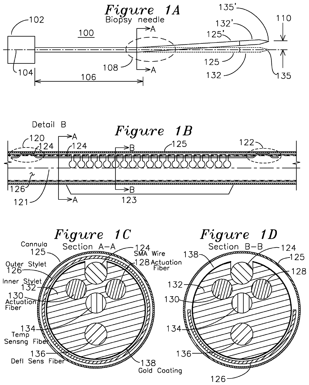
[0034]FIG. 1A shows the active elements of a steerable biopsy needle 100, including a cannula 125 which is optionally covered with a Teflon sheath or tube (not shown) to provide thermal isolation between the surrounding tissues and the thermally activated elements of the needle. According to a general object of the invention, the needle is steered using the axial asymmetry of the needle to create forces on the needle during its insertion. In this embodiment, the primary degrees of freedom to control needle direction are the insertion geometry and the axial rotation of the needle. Needles with asymmetric bevels at the tip are submitted to an unbalanced field of forces during the insertion. This phenomenon can be used to steer thin needles. Various complex insertion trajectory curves may be obtained by combining the needle insertion and self-rotation movements about the long axis 104 of the needle. The region of deflection 108 may be placed a distance 106 from the needle base 102, whi...


PUM


Abstract

A biopsy needle has a cylindrical shell outer cannula and a stylet consisting of an inner stylet and outer stylet, both of which are inserted into the cylindrical cannula. The outer stylet has a series of strain relieved slits which provide bending over a deflection region in one direction, and the outer stylet is formed from a material such as a shape memory alloy (SMA) having a superelastic phase. The deflection is generated by an SMA wire spanning a deflection extent and attached to the outer stylet on either side of the deflection extent. The inner stylet, when positioned inside the outer stylet, has one or more actuation fibers which couple optical energy into the SMA wire, causing a deflection of the outer stylet over the deflection extent, with the optical energy provided to the actuation fibers for control of the deflection.

Description

[0001]The present invention was developed under SBIR award No. 1142378 granted by the National Science Foundation (NSF) and NIH grant SBIR R43-EB011822. The government has certain rights in this invention.[0002]The present invention claims priority of provisional patent application 61 / 704,985 filed Sep. 24, 2012.FIELD OF THE INVENTION[0003]The present invention relates to a biopsy needle. In particular, the invention relates to a biopsy needle which is steerable and provides for measurement of deflection angle using shape sensing.BACKGROUND OF THE INVENTION[0004]In the field of interventional radiology, procedures such as biopsies or punctures are performed in combination with an imaging device which provides guidance during the biopsy procedure to a region of interest for the tissue sample. Magnetic Resonance (MR) scanners are useful imaging devices in this context: the radiologist and the patient are not exposed to any ionizing radiation, and the images provided by MR scanners pro...

Claims


Application Information

Patent Timeline
IPC IPC(8): A61B10/02A61B10/04A61B17/00A61B17/34
CPCA61B10/0275A61B10/04A61B17/3421A61B2017/003A61B2010/045A61B10/0233A61B34/20A61B2017/00084A61B2017/00309A61B2017/00853A61B2017/00867A61B2017/00907A61B2017/12072A61B2034/2061
Inventor RYU, SEOK CHANGCUTKOSKY, MARKBLACK, RICHARD J.COSTA, JOANNES MARIOMOSLEHI, BEHZADFARIDIAN, FEREYDOUNOBLEA, LEVYSOTOUDEH, VAHID
Owner INTELLIGENT FIBER OPTIC SYST
Why Eureka
Try Eureka