
Wireless inductive power transfer

a technology of inductive power transfer and wireless, which is applied in the direction of electrical equipment, circuit arrangements, etc., can solve the problems of increasing the weight, potential cost and size of the device, and the use of batteries, so as to achieve effective resonance frequency adjustment, facilitate implementation, and improve performance

Active Publication Date: 2020-07-07
KONINKLJIJKE PHILIPS NV
View PDF12 Cites 1 Cited by
  • Summary
  • Abstract
  • Description
  • Claims
  • Application Information

AI Technical Summary

Benefits of technology

The invention improves wireless power transfer systems and makes them more efficient. It also allows for better communication using load modulation. This can happen without the need for peak detection circuitry, which makes it simpler and more effective in many applications. Overall, the invention makes power transfer faster and more reliable based on load modulation.

Problems solved by technology

However, this tends to be impractical and requires the user to physically insert connectors or otherwise establish a physical electrical contact.
Although, the use of internal batteries may avoid the need for a wired connection to a power supply during use, this only provides a partial solution as the batteries will need recharging (or replacing).
The use of batteries may also add substantially to the weight and potentially cost and size of the devices.
However, with an increased distance between the resonance circuits, the load modulation communication from power receiver to power transmitter becomes increasingly difficult.
In resonant mode, the power transmitter's resonant circuit typically becomes underdamped which makes it sensitive to intermodulation distortion (with the intermodulation being between the resonance frequency of the power transmitter and the drive frequency).
Indeed, if the resonance frequency and the drive frequency of the power transmitter do not match, intermodulation frequencies appear, resulting in a degradation in communication performance, and often making the demodulation process at the power transmitter problematic or even impossible.
Suboptimal timing of the sampling may thus often result in the modulation performance being degraded.
However, such an approach tends to require additional, and often relatively complex, circuitry.
Further, such peak detection circuitry tends to be relatively inaccurate and thus the detected values often do not accurately reflect the underlying signal.
This may also result in degraded communication performance.

Method used


Image

  • Wireless inductive power transfer
  • Wireless inductive power transfer
  • Wireless inductive power transfer

Examples


Embodiment Construction

[0111]The following description focuses on embodiments of the invention applicable to a wireless power transfer system utilizing a power transfer approach such as known from the Qi specification. However, it will be appreciated that the invention is not limited to this application but may be applied to many other wireless power transfer systems.

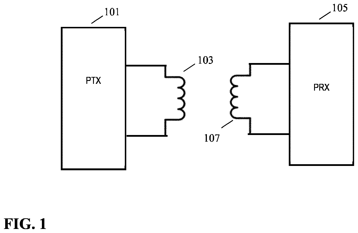
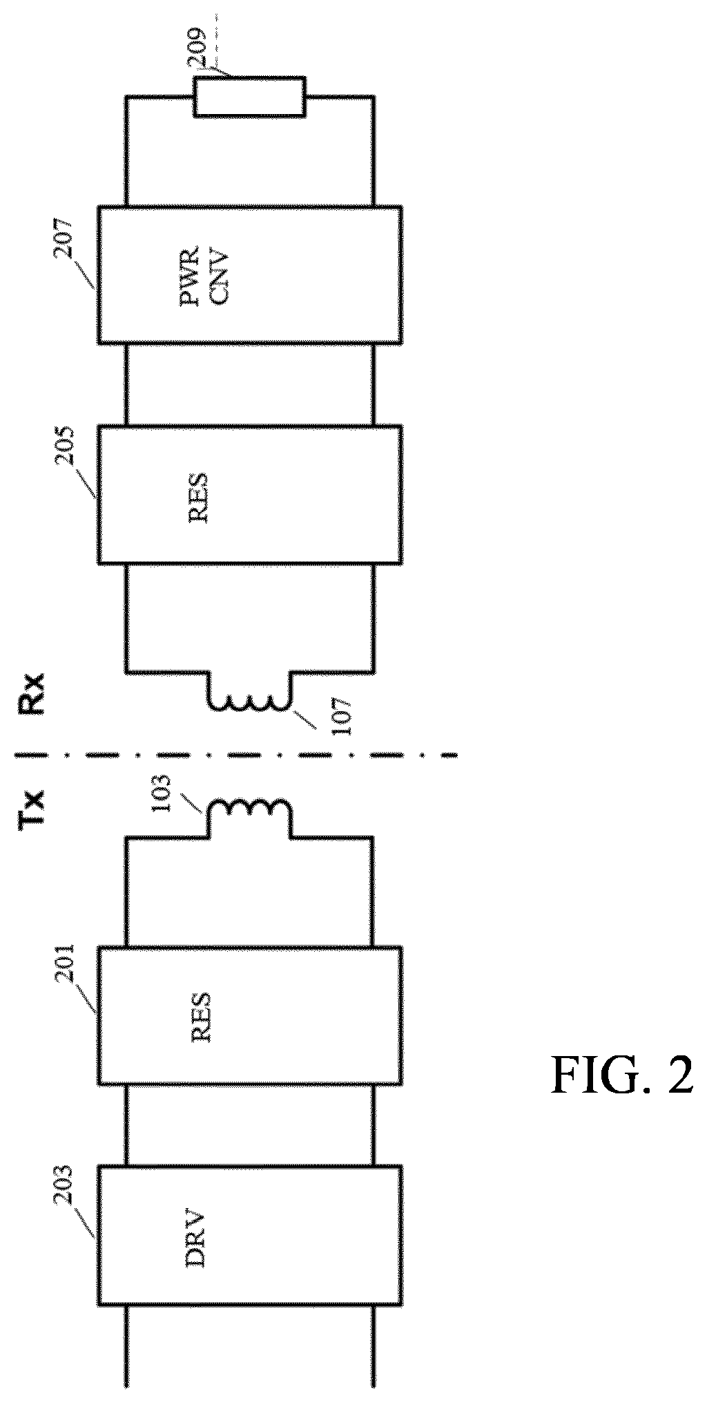
[0112]FIG. 1 illustrates an example of a power transfer system in accordance with some embodiments of the invention. The power transfer system comprises a power transmitter 101 which includes (or is coupled to) a transmitter inductor / inductor 103. The system further comprises a power receiver 105 which includes (or is coupled to) a receiver coil / inductor 107.

[0113]The system provides a wireless inductive power transfer from the power transmitter 101 to the receiver 105. Specifically, the power transmitter 101 generates a wireless inductive power transfer signal (also referred to as a power transfer signal, power transfer signal or an inductiv...


PUM


Abstract

A power transmitter (101) for inductively transferring power to a power receiver (105) comprises a resonance circuit (201) comprising a transmitter coil (103) for generating a power transfer signal. A sampler (511) samples a current through, or voltage over, the transmitter coil (103). A message receiver (509) receives messages load modulated onto the power transfer signal based on the samples. A driver (203) generates a drive signal for the resonance circuit (201) and a resonance modification circuit (505) reduces the resonance frequency of the resonance circuit (201) by slowing a state change for a resonating component of the resonance circuit (201) for a fractional time interval of the cycles of the drive signal. A sample time controller (513) controls the sample times in response to at least one of start-times and end-times of the fractional time intervals, and specifically may set the sample times to be within the fractional time intervals.

Description

CROSS-REFERENCE TO PRIOR APPLICATIONS[0001]This application is the U.S. National Phase application under 35 U.S.C. § 371 of International Application No. PCT / EP2016 / 076762, filed on 7 Nov. 2016, which claims the benefit of European Patent Application No. 15196289.1, filed on 25 Nov. 2015. These applications are hereby incorporated by reference herein.FIELD OF THE INVENTION[0002]The invention relates to inductive power transfer and in particular, but not exclusively, to a power transmitter providing inductive power transfer using elements compatible with the Qi Specifications for wireless power transfer systems.BACKGROUND OF THE INVENTION[0003]Most present day systems require a dedicated electrical contact in order to be powered from an external power supply. However, this tends to be impractical and requires the user to physically insert connectors or otherwise establish a physical electrical contact. Typically, power requirements also differ significantly, and currently most device...

Claims


Application Information

Patent Timeline
Patent Type & Authority Patents(United States)
IPC IPC(8): H02J50/12H02J50/80
CPCH02J50/12H02J50/80
Inventor JOYE, NEIL FRANCISLULOFS, KLAAS JACOB
Owner KONINKLJIJKE PHILIPS NV
Learn More