Liquid treatment device

a liquid treatment device and liquid treatment technology, applied in water/sewage treatment by electrochemical methods, water treatment compounds, specific water treatment objectives, etc., can solve the problems of high voltage needs to be applied, long time for liquid treatment, short life, etc., to achieve efficient generation, improve treatment performance, and reduce wear on the rod-like first electrode

Active Publication Date: 2020-07-28
PANASONIC INTELLECTUAL PROPERTY MANAGEMENT CO LTD
View PDF14 Cites 0 Cited by
  • Summary
  • Abstract
  • Description
  • Claims
  • Application Information

AI Technical Summary

Benefits of technology

[0018]With the liquid treatment device of the aspect of the present disclosure, the second electrode can serve as an anode and produce metal ions under the negative voltage applied between the first electrode and the second electrode by the DC power supply. For example, by making metal ions dissolve out from the plate-like second electrode through electrolysis, wears on the rod-like first electrode can be reduced, and a plasma can be efficiently generated for liquid treatment while at the same time improving treatment performance by taking advantage of the Fenton's reaction. This also enables stable plasma generation for a prolonged time period, and the system can operate for extended time periods. Because there is no need to vaporize liquid by voltage application, a plasma can be generated with a small power, and the liquid can be efficiently treated.

Problems solved by technology

A problem of the traditional liquid treatment device, however, is that a high voltage needs to be applied to vaporize the liquid, and the liquid treatment takes a long time because of the poor plasma generation efficiency.
However, the OH radicals that are generated in such a liquid treatment device are very reactive, and the life is short as they quickly turn into relatively stable hydrogen peroxide.
However, because the metal ions dissolve out of the rod-like positive electrode through electrolysis, the electrode severely wears out, and the life of the rod-like electrode is considerably cut short after a long treatment.
In the end, the device is no longer able to stably generate plasma.
That is, the system cannot operate for extended time periods.

Method used


Image

  • Liquid treatment device
  • Liquid treatment device
  • Liquid treatment device

Examples


embodiment

[0032]A liquid treatment device 100 according to an embodiment of the present disclosure is described below in detail, with reference to the accompanying drawings. In the drawings, the same or corresponding features are referred to by using the same reference numerals, and the same descriptions will not be repeated. To help understand the descriptions, the configurations in the drawings referred to in the following descriptions may be shown in simplified or schematic forms, or with omission of some of the constituting members. The dimensional ratios of the constituting members shown in the drawings are not necessarily true to the actual dimensional ratios.

Overall Configuration

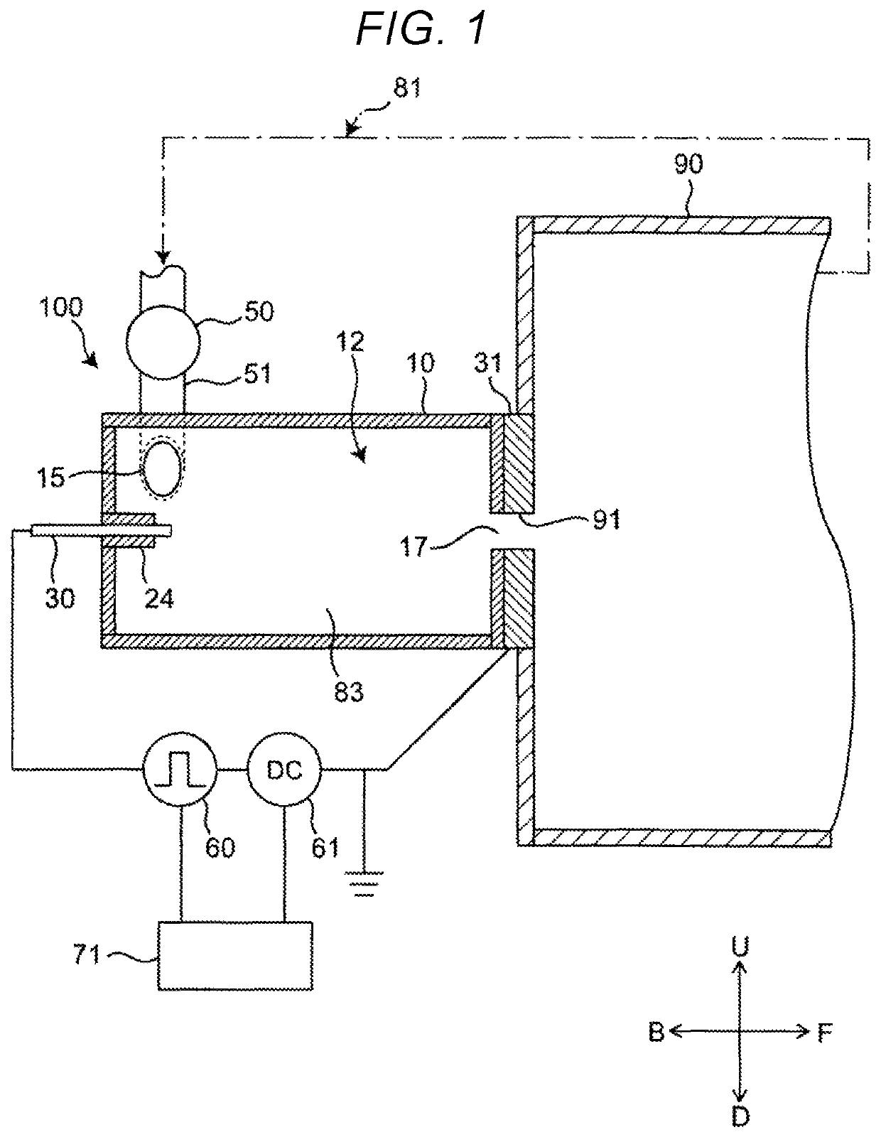
[0033]The overall configuration of the liquid treatment device 100 is described first. FIG. 1 is a side cross sectional view showing a configuration of the liquid treatment device 100 according to First Embodiment of the present disclosure. In the diagrams referred to below, the arrow F represents the front of ...


PUM

PropertyMeasurementUnit
negative offset voltageaaaaaaaaaa
negative voltageaaaaaaaaaa
voltageaaaaaaaaaa

Abstract

A liquid treatment device includes a rod-shaped first electrode; a plate-shaped second electrode configured from a metal containing copper or iron; and a treatment vessel in which introduced liquid swirls, and generates a gas phase in a swirl flow of the liquid. A plasma is generated by applying a pulse voltage to the generated gas phase, and a negative DC voltage is applied between the first electrode and the second electrode serving as a cathode and an anode, respectively. Under the applied negative voltage, the plate-like second electrode generates copper ions or iron ions, and the copper or iron ions undergo Fenton's reaction with the hydrogen peroxide generated by the plasma so that liquid can be efficiently treated.

Description

[0001]This application claims foreign priority to Japanese Patent Application No. JP 2017-231766, filed on Dec. 1, 2017.TECHNICAL FIELD[0002]The technical field relates to a liquid treatment device that electrochemically treats liquid. Specifically, the present disclosure relates to a liquid treatment device that treats liquid with a plasma generated in the liquid, whereby contaminants and microorganisms contained in the liquid are decomposed and sterilized by the plasma directly contacting these substances, and simultaneously by the ultraviolet (UV) light and radicals generated by plasma discharge.BACKGROUND[0003]FIG. 10 shows a traditional liquid treatment device. A first electrode 801 and a second electrode 802 are disposed in liquid 803 (for example, water), and a pulse power supply 804 applies a high-voltage pulse across the electrodes 801 and 802 to vaporize the liquid 803 and generate a plasma 805. Here, contaminants and other foreign substances contained in the liquid 803 ar...

Claims


Application Information

Patent Timeline
Patent Type & Authority Patents(United States)
IPC IPC(8): C02F1/46C02F1/461B01J19/26H05H1/00B01J19/00
CPCC02F1/4608C02F1/46109C02F2001/46133C02F2303/04C02F2201/46135C02F2201/4617C02F2305/023C02F2305/026B01J2219/0894C02F2001/46171C02F2201/46175
Inventor MATSUDA, GENICHIROKITAI, TAKAHIROMIYAKE, GAKUYAMADA, YOSHIO
Owner PANASONIC INTELLECTUAL PROPERTY MANAGEMENT CO LTD
Why Eureka
Try Eureka