
Methods for interpreting NMR data

a nuclear magnetic resonance and data technology, applied in the field of methods for interpreting nuclear magnetic resonance (nmr) data, can solve the problem that the insufficient fluid-phase contrast mechanism of the inherent fluid-phase phase is not sufficient to discriminate the phases

Active Publication Date: 2020-07-28
SCHLUMBERGER TECH CORP
View PDF21 Cites 1 Cited by
  • Summary
  • Abstract
  • Description
  • Claims
  • Application Information

AI Technical Summary

Benefits of technology

The present patent provides methods for improving the interpretation of NMR data from petrophysical samples by simultaneously detecting multiple resonant nuclei without removing the sample from the NMR magnet or radio frequency probe. The methods can be used for analyzing samples such as crude oil, brine, gas, drilling mud, and underground reservoirs. The detection of multiple resonant nuclei allows for the robust and quantitative determination of volumes of different fluids in the pores of a rock sample. The methods can be used in real-time to screen for enhanced oil recovery techniques and products and improve the interpretation of well-logs. The patent also discusses the use of additional information obtained from changes in relaxation behavior at different magnetic field strengths to improve analysis of complex dynamics inside porous media and infer fluid-pore interactions.

Problems solved by technology

However, there are cases where these inherent fluid-phase contrast mechanisms are insufficient to discriminate the phases, e.g., mud filtrate invasion in pre-salt carbonate formations.

Method used


Image

  • Methods for interpreting NMR data
  • Methods for interpreting NMR data
  • Methods for interpreting NMR data

Examples


example 1

ane Emulsions

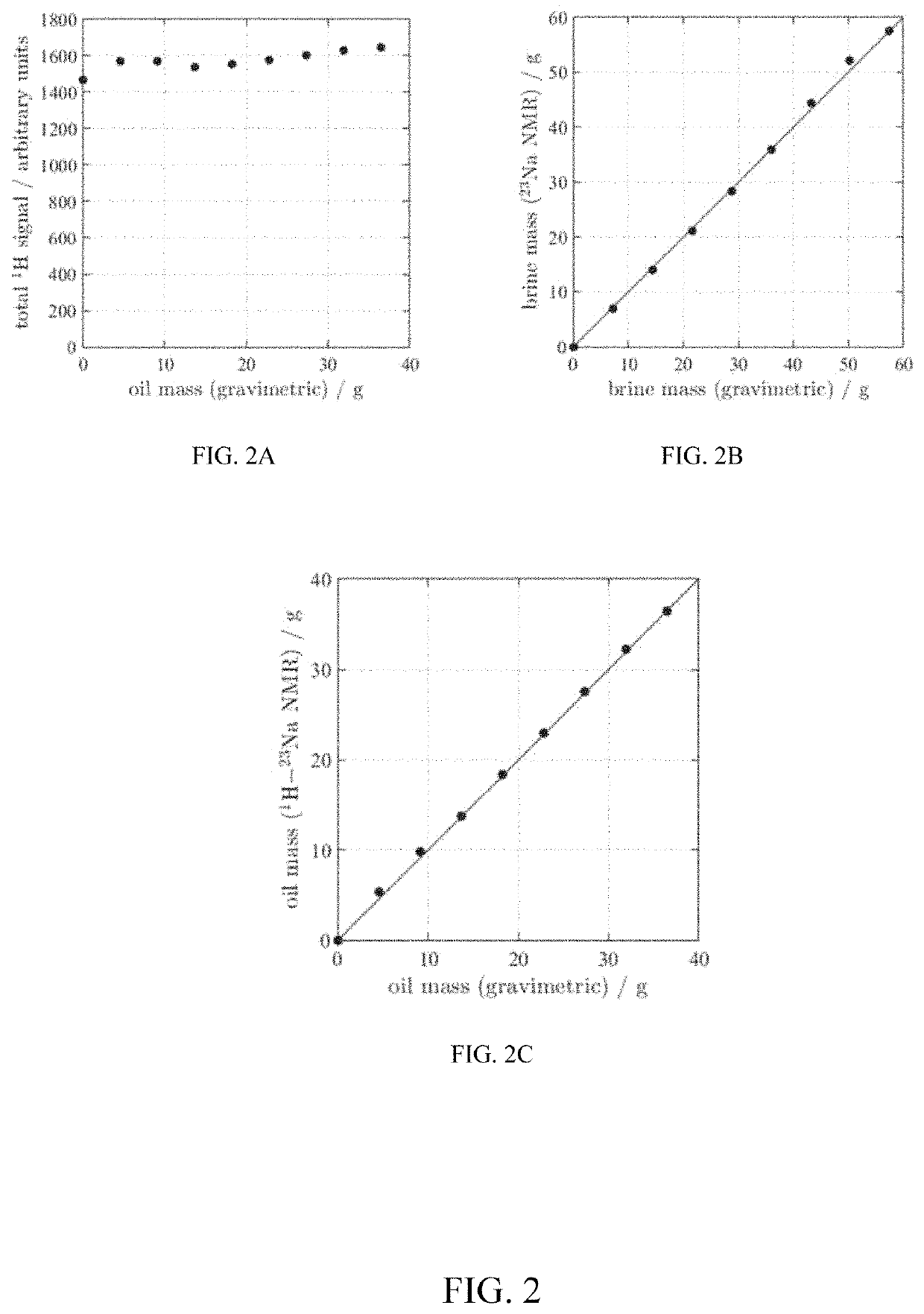
[0047]FIG. 2 shows an example of dual resonance detection in accordance with one or more embodiments of the present disclosure. In particular, FIG. 2 shows the example of dual resonance detection of 1H / 23Na for quantification of oil and brine in emulsion samples in the forms of total 1H signal as a function of oil fraction (FIG. 2A), brine mass determined by 23Na (FIG. 2B), and oil mass determined by difference in 1H and 23Na measurements (FIG. 2C).

[0048]A series of emulsion samples were generated ranging from 100% brine to 100% decane. The ratio of oil and brine was varied linearly between these two extremes. Standard 1H contrast mechanisms of T2 relaxation time or diffusion coefficient are unable to distinguish between oil and brine in these samples (see below for further details). To quantify the mass of oil and brine in each sample, a combination of 1H and 23Na measurements were used. The total 1H and 23Na signal amplitudes were obtained for each sample. Using the e...

example 2

ery Monitoring

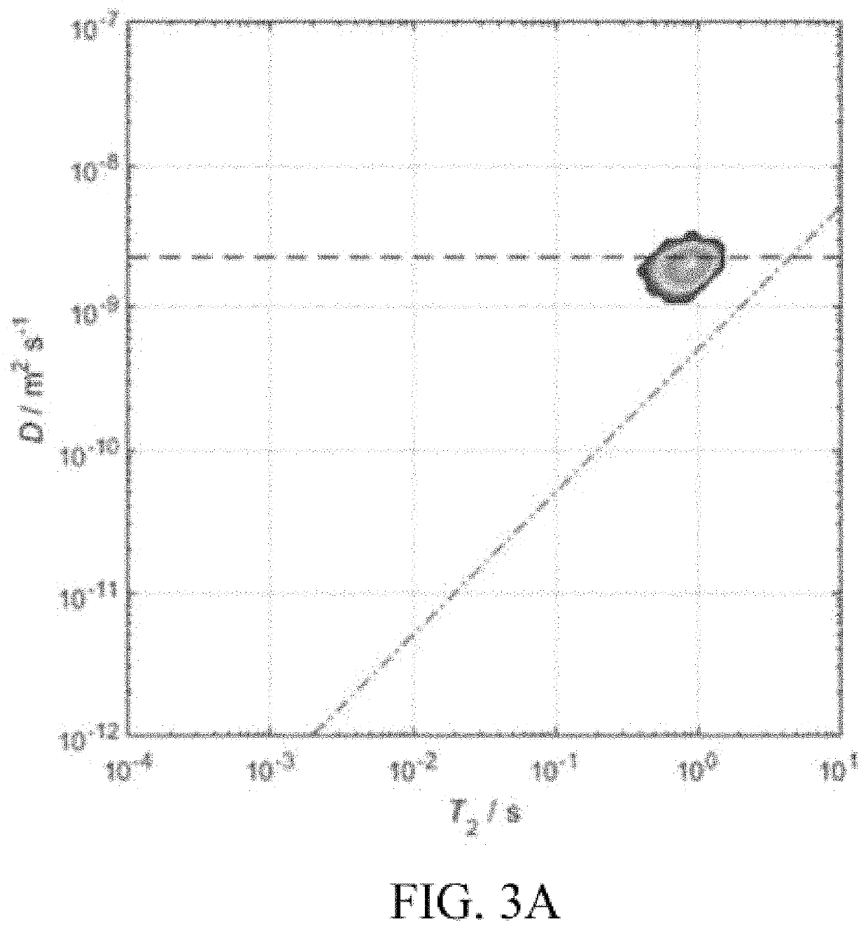
[0054]The methods described in “Example 1” above are now demonstrated in FIGS. 3A through 3C in an example of dual resonance detection in a rock plug in accordance with one or more embodiments of the present disclosure. In particular, FIGS. 3A through 3C show coreflood monitoring of decane displaced by high-salinity brine in a Bentheimer sandstone plug. Conventional 1H D-T2 correlation plots are unable to distinguish between the cases of fully brine saturated (FIG. 3A) and 80% oil saturated (FIG. 3B). However, using 1H and 23Na detection, the oil and brine saturations can be monitored during the coreflood. The variation in saturation state as a function of time (volume brine injected) is shown in FIG. 3C.

[0055]The rock, a Bentheimer sandstone, was initially saturated with a high-salinity brine. The rock was mounted in a NMR-compatible rock core holder; details of the ErgoTech core holder are given in Tutunjian, P. N., Vinegar, H. J., Ferris, J. A., 1993. Nuclear magnet...

example 4

reflood Monitoring

[0064]Another example shows a combined 1H and 23Na measurement to monitor changes in both oil / brine saturation and salinity (sodium-salt content) during a low-salinity (Lo-Sal) coreflood. Lo-Sal waterflooding is a form of EOR, although the exact mechanism by which the change in salinity mobilizes additional oil is not well understood. The ability to monitor both the in situ oil saturation (with 1H NMR) and the salt content (with 23Na NMR) can provide new insights into the recovery mechanisms of Lo-Sal water flooding. For example, spatially resolved measurements will show whether the additional recovery of oil due to low-salinity brine is uniform along the core-plug or associated only with, say, a capillary end effect. An example of monitoring both oil saturation and salt content during a low-salinity coreflood is given in FIG. 5. In particular, FIG. 5 shows displacement of L2 oil from Estaillades limestone by (i) high-salinity brine and (ii) low-salinity brine. The...


PUM

PropertyMeasurementUnit
pore body sizeaaaaaaaaaa
nuclear magnetic resonanceaaaaaaaaaa

Abstract

Methods for improved interpretation of NMR data acquired from industrial samples by simultaneously detecting more than one resonant nucleus without removing the sample from the sensitive volume of the NMR magnet or radio frequency probe are disclosed. In other aspects, the present disclosure provides methods for robust imaging / analysis of spatial distribution of different fluids (e.g., 1H, 23Na, 19F) within a core or reservoir rock. NMR data may be interpreted in real-time during dynamic processes to enable rapid screening, e.g. of enhanced oil recovery techniques and products and / or to provide improved interpretation of well-logs. Measurements of resonant nuclei other than 1H may be performed in the laboratory or downhole with a NMR logging tool. In other aspects, the present disclosure describes a novel kernel function to extract values for underlying parameters that define relaxation time behavior of a quadrupolar nucleus.

Description

CROSS-REFERENCE TO RELATED APPLICATION[0001]This application claims the benefit of U.S. Provisional Application No. 62 / 383,242, filed Sep. 2, 2016.BACKGROUND[0002]This section is intended to introduce the reader to various aspects of art that may be related to various aspects of the presently described embodiments. This discussion is believed to be helpful in providing the reader with background information to facilitate a better understanding of the various aspects of the described embodiments. Accordingly, it should be understood that these statements are to be read in this light and not as admissions of prior art.[0003]The present disclosure relates to methods for interpreting nuclear magnetic resonance (NMR) data. In particular, but not by way of limitation, this disclosure relates to relates to interpretation of NMR data by simultaneously detecting more than one resonant nucleus.[0004]Spatially resolved measurements have been applied to monitoring oil recovery from small rock s...

Claims


Application Information

Patent Timeline
Patent Type & Authority Patents(United States)
IPC IPC(8): G01V3/32G01V3/38G01N33/24E21B49/00
CPCG01V3/38G01V3/32E21B49/00Y02A90/344G01N33/24Y02A90/30
Inventor MITCHELL, JONATHANFORDHAM, EDMUND J.ZIELINSKI, LUKASZKADAYAM VISWANATHAN, RAVINATH KAUSIK
Owner SCHLUMBERGER TECH CORP
Learn More