
Laser exposure head with reduced leakage

a technology of exposure head and laser, which is applied in the field of laser printers, can solve the problems of desensitizing the system, expensive system, and difficult maintenance in the manufacturing environment, and achieves the effects of reducing the leakage level, increasing the depth of focus, and increasing the power level

Active Publication Date: 2020-09-01
EASTMAN KODAK CO
View PDF14 Cites 0 Cited by
  • Summary
  • Abstract
  • Description
  • Claims
  • Application Information

AI Technical Summary

Benefits of technology

The system achieves significantly reduced leakage, increased power, and improved depth of focus compared to prior art configurations, with leakage rates as low as 1.5% compared to 8% in conventional designs, while maintaining high image quality and resolution.

Problems solved by technology

However, these systems are significantly disadvantaged as the failure of even one lasing element or emitter of the laser diode array source will appear as an artifact in the printed image, requiring replacement of the entire laser array source.
This approach desensitizes the system to the failure of the lasing elements or emitters within a subarray.
Also, as the light from the emitters overlaps in illuminating the modulator, the resulting redundancy desensitizes the system to the failure or poor behavior of any of the lasing elements or emitters within the array.
While this may be achievable within the constraints shown in U.S. Pat. No. 4,786,918, the care, detail and effort required may render the system expensive and difficult to maintain in a manufacturing environment.
Useful materials are preferably highly transmissive in the near infrared, and have a high threshold to optical damage.
However, the high-power laser sources needed for laser thermal printing applications are at best partially coherent.
However, experience shows that reduction of grating period in TIR modulators leads to increase of leakage to levels greater than 5%.
Such leakage levels would create unacceptable artifacts in many applications.

Method used


Image

  • Laser exposure head with reduced leakage
  • Laser exposure head with reduced leakage
  • Laser exposure head with reduced leakage

Examples


Embodiment Construction

[0030]The invention is inclusive of combinations of the embodiments described herein. References to “a particular embodiment” and the like refer to features that are present in at least one embodiment of the invention. Separate references to “an embodiment” or “particular embodiments” or the like do not necessarily refer to the same embodiment or embodiments; however, such embodiments are not mutually exclusive, unless so indicated or as are readily apparent to one of skill in the art. The use of singular or plural in referring to the “method” or “methods” and the like is not limiting. It should be noted that, unless otherwise explicitly noted or required by context, the word “or” is used in this disclosure in a non-exclusive sense.

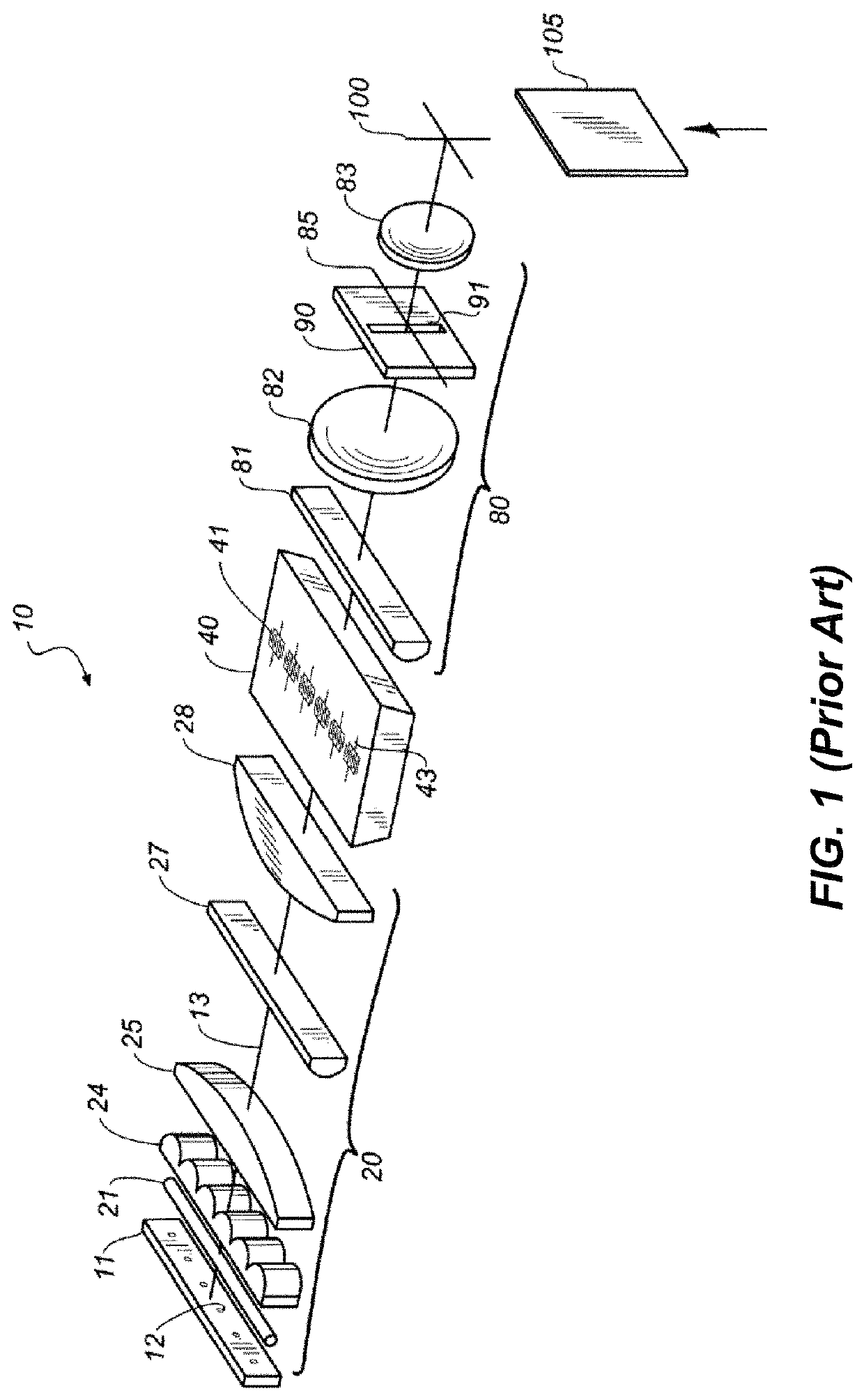
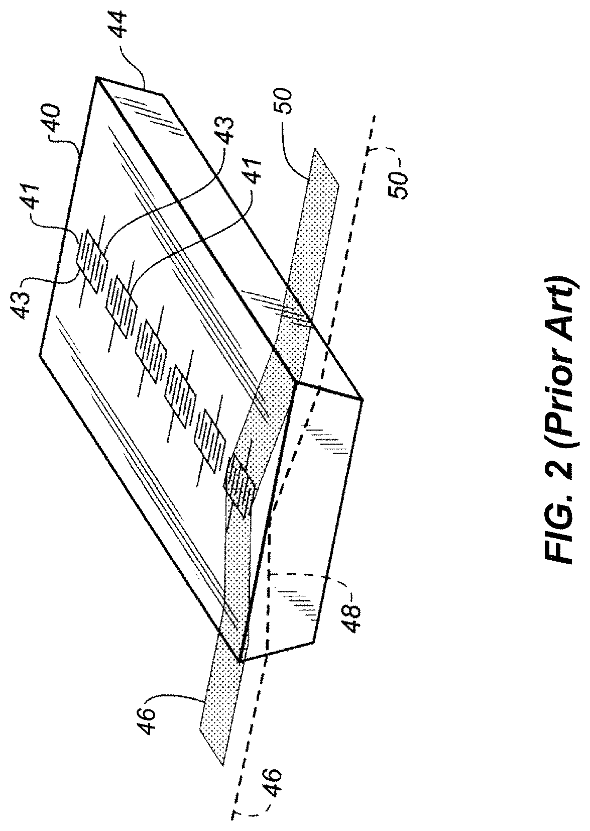
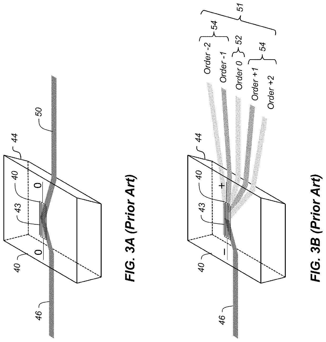
[0031]FIG. 1 illustrates an exemplary laser exposure system 10 (i.e., a laser printer) as described in commonly-assigned U.S. Pat. No. 6,169,565 to Ramanuj an et al., entitled “Laser printer utilizing a spatial light modulator,” which is incorporated here...


PUM

PropertyMeasurementUnit
aspect ratioaaaaaaaaaa
widthaaaaaaaaaa

Abstract

A laser exposure system includes an electrically-controlled diffraction grating which can be controlled to be in a first state where the incident light beam is undiffracted and a second state where the incident light beam is diffracted into a plurality of light beams including a zero-order light beam and first and second diffracted light beams. An aperture structure which passes the first and second diffracted light beams while blocking the zero-order light beam. A polarization rotator rotates a polarization state of the second diffracted light, and a polarization beam combiner combines the first diffracted light beam and the polarization-rotated second diffracted light beam onto a common path forming a combined light beam. An optical element focuses the combined light beam onto an imaging medium. A controller controls the state of the electrically-controlled diffraction grating in accordance with pixel data to form a printed image.

Description

FIELD OF THE INVENTION[0001]This invention pertains to the field of laser printers, and more particularly to laser exposure heads using electro-optic spatial light modulators.BACKGROUND OF THE INVENTION[0002]Laser printers, particularly flying spot printers, are used in a wide variety of applications, from office printing, to medical printing, to bar code printing. These systems typically print with a single lower power beam, onto fairly sensitive media. Other systems, such as those used in the graphic arts industry, often are configured as multispot printers to attain sufficient productivity. As many types of graphic arts media are rather insensitive to light exposure, each of these incident beams must provide a high light level in a small spot at the printing plane. Such printers are typically configured like a “lathe,” where the page scan is obtained by rotating a drum which holds the media, and the line scan is obtained by translating the multiple laser beams in a direction para...

Claims


Application Information

Patent Timeline
Patent Type & Authority Patents(United States)
IPC IPC(8): G02F1/29G02F1/315B41J2/44G02F1/07G02F1/03G02B5/00G02B27/28
CPCB41J2/442G02F1/315G02F2201/305G02B27/283G02B5/005B41J2/465B41J2/451
Inventor KARASSIOUK, VALENTINE A.PILOSSOF, NISSIM
Owner EASTMAN KODAK CO
Learn More