Supercharge Your Innovation With Domain-Expert AI Agents!

Time-to-digital converter and phase difference detection method

a time-to-digital converter and detection method technology, applied in the field of integrated circuits, can solve the problems of low detection accuracy of time difference, significant increase of required power consumption and chip area of the conventional scheme, and inability to meet the requirements of high-precision time difference detection. , to achieve the effect of saving chip area and power consumption, avoiding detection errors

Active Publication Date: 2020-11-03
MONTAGE TECHNOLOGY CO LTD
View PDF7 Cites 0 Cited by
  • Summary
  • Abstract
  • Description
  • Claims
  • Application Information

AI Technical Summary

Benefits of technology

This patent is about a new technology for detecting time differences in clock signals. The technology improves accuracy and reduces the amount of space and power consumed on a chip. It uses a time-to-digital converter and a distributed structure with multiple detection units. The delay time of reference signals is adjusted using a single digital control circuit, which helps save chip area and power. Overall, this technology helps to make more accurate and efficient timing measurements in electronic devices.

Problems solved by technology

The conventional scheme described above has low detection accuracy of time difference and is not suitable for high-precision time difference detection due to the limitations of sampling accuracy and output metastable interval of the D trigger.
Meanwhile, the required power consumption and chip area of the conventional scheme are significantly increased with the improvement of detection range and precision, which is not suitable for low-cost and low-power applications.

Method used


Image

  • Time-to-digital converter and phase difference detection method
  • Time-to-digital converter and phase difference detection method
  • Time-to-digital converter and phase difference detection method

Examples


Embodiment Construction

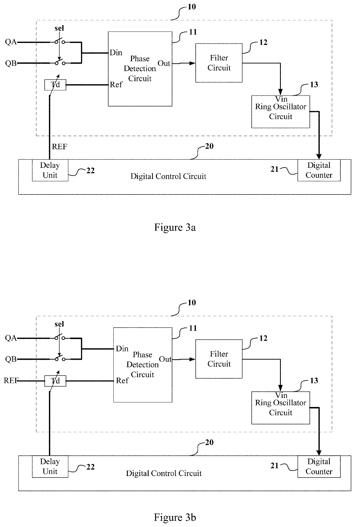
>[0041]The present application discloses a time-to-digital converter, as shown in FIG. 3a, comprising a detection unit 10 and a digital control circuit 20, wherein the detection unit 10 includes a phase detection circuit 11, a filter circuit 12 and a ring oscillator circuit 13.

[0042]A first clock signal QA and a second clock signal QB to be detected are respectively coupled to an identical input terminal Din of the phase detection circuit 11. Specifically, the first clock signal QA and the second clock signal QB are separately coupled to the terminal Din of the phase detection circuit 11 via respective switches. One of the first clock signal QA and the second clock signal QB is input to the input terminal Din of the phase detection circuit 11 according to a control signal sel (for example, the first clock signal QA is input to the input terminal Din of the phase detection circuit 11 when the control signal sel is at a low level, the second clock signal QB is input to the input termi...


PUM


Abstract

A time-to-digital converter and a phase difference detection method are disclosed. The time-to-digital converter includes a detection unit and a digital control circuit. The detection unit comprising: a phase detection circuit, a first and a second clock signal are respectively coupled to an identical input terminal of the phase detection circuit and a reference signal is coupled to another input terminal of the phase detection circuit; the phase detection circuit is configured to output a pulse width corresponding to a phase difference between the first or the second clock signal and the reference signal; a filter circuit, coupled to an output terminal of the phase detection circuit; a ring oscillator circuit, coupled to an output terminal of the filter circuit and configured to output an oscillation clock signal corresponding to the pulse width. The digital control circuit is configured to provide the reference signal and receive the oscillation clock signal.

Description

TECHNICAL FIELD[0001]This disclosure generally relates to an integrated circuit, particularly to a time-to-digital converter and a phase difference detection method.BACKGROUND OF THE INVENTION[0002]Conventional structure of time-to-digital converter is as shown in FIG. 1. The time-to-digital converter comprises a set of delay units 2 connected in series and a set of D triggers 1, each delay unit 2 cooperates with one trigger 1. A start signal and a stop signal are input signals to be detected. The start signal passes through sequentially the set of the delay units and a set of delayed start signals D<N:0> are respectively output by the set of the delay units. The trigger may record a time difference between the stop signal and the corresponding delayed start signal. Working process of the time-to-digital converter is shown as FIG. 2, the stop signal is used as a sampling clock signal, each delayed start signal is sampled by rising edge of the stop signal, and signals Q<N:0&...

Claims


Application Information

Patent Timeline
Patent Type & Authority Patents(United States)
IPC IPC(8): H03L7/093G04F10/00H03L7/099
CPCH03L7/0995G04F10/005H03L7/093G01R25/00
Inventor ZHANG, PENGZHANWANG, YONGLI, YANHONGWU, YAOMINCHANG, ZHONGYUAN
Owner MONTAGE TECHNOLOGY CO LTD
Features
  • R&D
  • Intellectual Property
  • Life Sciences
  • Materials
  • Tech Scout
  • Unparalleled Data Quality
  • Higher Quality Content
  • 60% Fewer Hallucinations
Learn More