

Hydraulic system with servo drive and hydraulic load and control unit for the hydraulic system
a hydraulic system and hydraulic system technology, applied in the direction of servomotors, programme control, instruments, etc., can solve the problems of electric motor turning backwards, mechanical load torque may also become negative, and high acceleration of motor speed is required for a rapid increase or decrease of system pressur
- Summary
- Abstract
- Description
- Claims
- Application Information
AI Technical Summary
Benefits of technology
Problems solved by technology
Method used
Image

Examples
Embodiment Construction
[0004]Embodiments better utilize and protect a possible range of the mechanical load torque of a servo drive in combination with a pump.
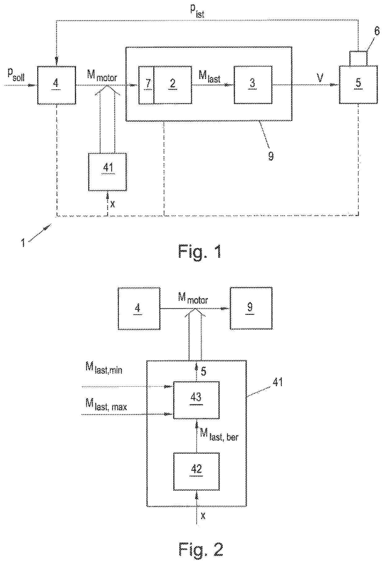
[0005]According to embodiments, a method and a device, wherein a dynamic system variable of the hydraulic system is transmitted to a limiting unit, and the limiting unit is limited by the motor torque transmitted by the control unit to the electric motor as a function of the value of the system variable. Compared to the specified fixed limits of the motor torque, the solution according to the invention has the advantage that the motor torque can be limited in a highly dynamic manner as a function of the current value of a variable system parameter, e.g., actual system pressure, motor speed, and so on. In this way, one can respond to the current operating state of the hydraulic system on a case-by-case basis. (Electrical) motor torques may thereby be generated, which exceed conventional maximum and minimum limits of the motor torque specified in prio...
PUM
 Abstract
Description
Claims
Application Information