Reactivation of catalyst for lean NOx trap

Active Publication Date: 2020-11-24
GM GLOBAL TECH OPERATIONS LLC
View PDF1 Cites 0 Cited by
  • Summary
  • Abstract
  • Description
  • Claims
  • Application Information

AI Technical Summary

Benefits of technology

[0013]Example illustrations are also directed to an exhaust system for a vehicle, which may include a catalytic converter positioned in an exhaust tailpipe, the catalytic converter configured to reduce a concentration of a nitrogen-oxide (NOx) present in an exhaust flow through the catalytic converter, and a temperature sensor positioned such that the temperature sensor is configured to determine an operating temperature of the catalytic converter. The system may also include a processor in communication with the temperature sensor. The processor may be configured to determine a catalytic converter in an exhaust system is at least partially deactivated by detecting (1) an exhaust temperature above a temperature threshold and (2) an air-fuel equivalence ratio of a hydroca

Problems solved by technology

Lean air-fuel mixtures may generally reduce fuel consumption of internal combustion (IC) engines, but typically cause increased emissions of nitrogen-oxides (NOx) in an exhaust flow from the engine.
When a catalytic converter is exposed to relatively high temperatures in lea

Method used


Image

  • Reactivation of catalyst for lean NOx trap
  • Reactivation of catalyst for lean NOx trap
  • Reactivation of catalyst for lean NOx trap

Examples


Embodiment Construction

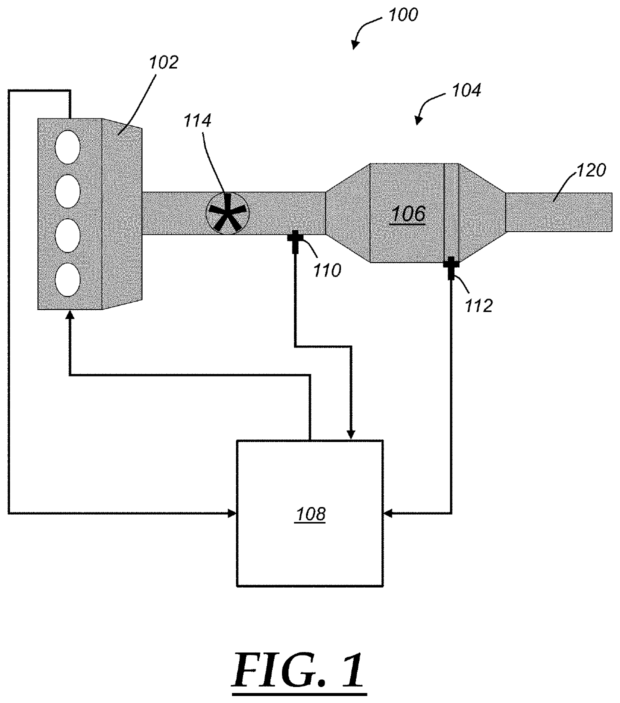
[0023]Example methods and systems described herein may generally detect a deactivation of a catalytic converter. As will be discussed further below, a deactivation of a catalytic converter may occur during a lean-burn engine operation while the catalytic converter is exposed to relatively high temperatures. Deactivation may thus be detected monitoring catalyst temperature and exposure time at that temperature. Additionally, a deactivation level may be determined, which may be used to identify corrective measures to reactivate the catalyst. A deactivation level or extent to which the catalyst has been deactivated may be determined from an exhaust or catalytic converter temperature, an exposure time at the elevated temperature, and also a space velocity or flow rate associated with the exhaust through the catalytic converter. Example reactivation strategies may include a temporary period of an enriched air-fuel ratio, which may include one or more intermittent “pulses” of an enriched ...


PUM


Abstract

Example methods and systems for treating exhaust from an internal combustion engine may generally determine a catalytic converter in an exhaust system is at least partially deactivated by detecting an elevated exhaust temperature and a lean-burn operating condition. In response, a deactivation level of the catalytic converter may be determined, which may be compared with a threshold deactivation level. A magnitude of a temporary rich-fuel operating condition as a response may be determined based upon the comparison. The catalytic converter may be reactivated with the temporary rich-fuel operating condition.

Description


Claims


Application Information

Patent Timeline
Owner GM GLOBAL TECH OPERATIONS LLC
Why Eureka
Try Eureka