
Connective tissue to bone interface scaffolds

a technology of connective tissue and bone interface, applied in the field of connective tissue to bone interface scaffolds, can solve the problems of rotator cuff injuries that are particularly prevalent and difficult to repair, dull ache in the shoulder, and the risk of rotator cuff injuries increases with ag

Active Publication Date: 2021-04-06
SPARTA BIOPHARMA LLC
View PDF57 Cites 2 Cited by
  • Summary
  • Abstract
  • Description
  • Claims
  • Application Information

AI Technical Summary

Benefits of technology

The patent describes a new type of graft that can be used to repair bones. The graft has a soft, flexible body that allows it to be easily inserted into the bone marrow spaces using a needle. The graft is made with a high degree of porosity, which allows fluids and cells to quickly incorporate into it, promoting bone growth. The graft can also have sutures pre-formed through it to make it easier for the surgeon to secure it in place. The graft is highly deformable and can conform to the bone's attachment sites, minimizing damage. The graft is made with a thin, flexible outer layer that allows for easy insertion and does not compromise its mineralized layer. The graft's different layers can be easily distinguished using a biocompatible dye.

Problems solved by technology

In particular, rotator cuff injuries are particularly prevalent and difficult to repair.
A rotator cuff injury can cause a dull ache in the shoulder, which often worsens when you try to sleep on the involved side.
The risk of rotator cuff injury increases with age.
Extensive rotator cuff tears typically require surgical repair, however current techniques are not optimal, and may be difficult or impossible to achieve, or may fail days or months after surgery.
In particular, reattachment of connective tissue, including rotator cuff tissue, to bone is notoriously difficult to achieve.
Without such integration, mechanical stability is limited at the joint and the lack of integration can produce higher rates of graft failure.
However, most of these studies focus on the midsubstance region and fail to address the regeneration of the interface.
Unfortunately for many tissues, especially those in the musculoskeletal system, matching the mechanical properties is not sufficient.
Further, full mobility and pain relief are not generally possible.
Although bone implants for repairing damaged ligaments and tendons from bone have been proposed (e.g., U.S. Pat. Nos. 6,776,800, 6,855,169, 7,753,963, and 8,702,809), these implants have been difficult to implement.
In particular, these implants have required hinge regions or other techniques for making them flexible, often compromising their strength and structural integrity and requiring complex fabrication processes.

Method used


Image

  • Connective tissue to bone interface scaffolds
  • Connective tissue to bone interface scaffolds
  • Connective tissue to bone interface scaffolds

Examples


Embodiment Construction

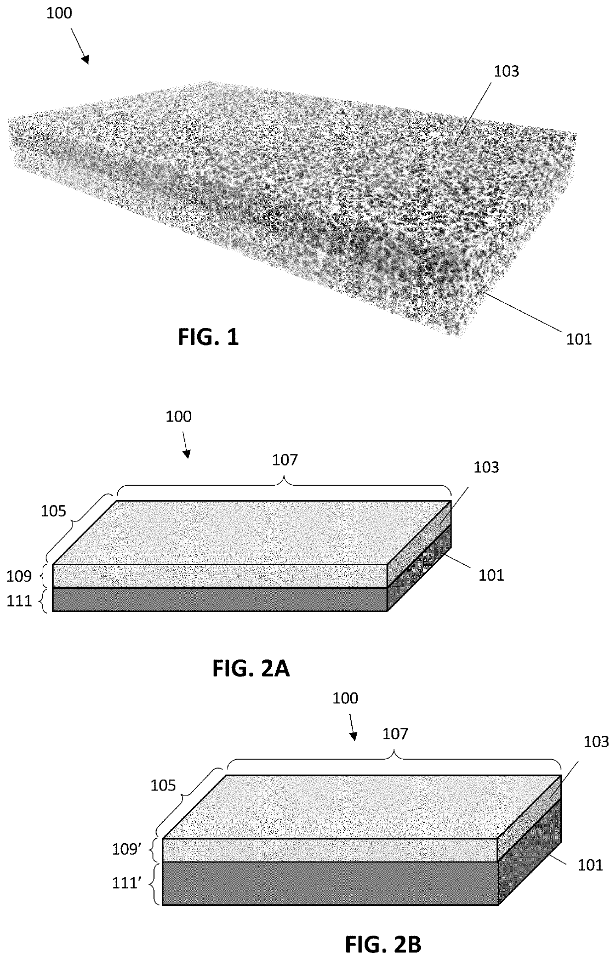
[0045]Described herein are connective tissue-to-bone interface scaffolds (e.g., grafts) that are adapted and configured for surgical implantation onto bone to allow ingrowth of both bone as well as connective tissue. These grafts may be particularly well adapted for implantation and attachment as part of a minimally-invasive, e.g., arthroscopic, laparoscopic, surgery.

[0046]For example, FIG. 1 shows one example of a tissue-to-bone interface scaffold as described herein 100. In FIG. 1, the scaffold includes a first, demineralized layer 101 and a second mineralized layer 103. As will be described in detail below, the dimensions of the mineralized and demineralized layers, and in particular, their ratios, may be selected within a desired range to optimize both the ease of using them in the particular surgical procedures described herein, as well as for stability and in-growth of connective tissue and / or bone. In FIG. 1 the mineralized and demineralized portions are both porous, although...


PUM

PropertyMeasurementUnit
Lengthaaaaaaaaaa
Lengthaaaaaaaaaa
Lengthaaaaaaaaaa

Abstract

Connective tissue-to-bone interface scaffolds (e.g., ligament-to-bone interface scaffolds, tendon-to-bone interface scaffolds, etc.). These scaffolds may be a single integrated implant or may be a modular (e.g., two-part) implant system.

Description

CROSS REFERENCE TO RELATED APPLICATIONS[0001]This patent application claims priority to U.S. Provisional Patent Application No. 62,923,470, titled “CONNECTIVE TISSUE TO BONE INTERFACE SCAFFOLDS,” filed on Oct. 18, 2019, and U.S. Provisional Patent Application No. 63 / 069,658, titled “CONNECTIVE TISSUE TO BONE INTERFACE SCAFFOLDS,” filed on Aug. 24, 2020 each of which is herein incorporated by reference in its entirety.INCORPORATION BY REFERENCE[0002]All publications and patent applications mentioned in this specification are herein incorporated by reference in their entirety to the same extent as if each individual publication or patent application was specifically and individually indicated to be incorporated by reference.FIELD[0003]Described herein are scaffolds for repair of the enthesis, including ligament to bone and tendon to bone interface scaffolds for repair of torn tendons, ligaments, and / or calcified and uncalcified fibrocartilage.BACKGROUND[0004]Connective tissues, includ...

Claims


Application Information

Patent Timeline
IPC IPC(8): A61L27/36A61F2/08A61F2/28A61F2/30
CPCA61F2/0811A61F2/2846A61L27/3604A61L27/3608A61F2002/0823A61F2002/0876A61F2002/2835A61F2002/30059A61F2002/30448A61F2210/0076A61F2220/005A61F2220/0075A61F2250/006A61F2002/285A61F2002/30461A61F2310/00359A61L27/38A61L27/54A61L27/56A61L27/58A61L27/18A61F2002/087C08L67/04
Inventor SURAKANTI, DUSHYANTH R.YANKE, ADAM B.MARTINEZ, ADAM W.KLITZKE, KURT W. S.ENTROP, TRAVIS E.ANGELIS, DIMITRIOS J.NAUMAN, ERIC A.DICKERSON, DARRYL A.
Owner SPARTA BIOPHARMA LLC
Learn More