These real time adjustments are limited in range to those conditions permitted by the “
recipe” that defines the production.
Out-of-range conditions typically cause the process to halt until an operator can intervene and correct the condition.
However, PA systems often cannot control process
automation systems due to the disparate nature of the two types of systems.
For example, when a customer orders a part with specific colors, dimensions, or other physical attributes, the traditional
process automation system may supply a computer assisted manufacturing
system with specifications to manufacture that part, but does not actually manage the manufacturing processes.
Because of these differences, constructing a
hybrid synchronous and asynchronous
process management system is generally not a simple combination of the two (or more) technologies.
Once a
defined process workflow has been compiled, it is typically difficult or impossible to alter the compiled process without re-compiling the defined
workflow (e.g. the BPEL) and restarting all currently executing
workflow instances.
This limits the flexibility of these systems in the face of unexpected process states, system outages, and / or
partial system failures.
These limits are often evidenced when workflows get “stuck” waiting for a resource that never becomes available, a change in
process state that never occurs, or where processes simply “slow down” to unaccepted performance levels as their constituent process components are slowed.
Once set, the pre-defined workflow steps, paths, and
decision points, and the computing resources assigned to implement them cannot automatically be changed in response to changing operational conditions.
In particular, changes to the workflow cannot be made “
on the fly” in response to real-time inputs such as supply interruptions, inaccuracies in underlying decision databases, or even in response to system and / or network errors.
The workflow also cannot compensate for other operational issues that are not a failure, e.g. process slowdowns due to system overload or communication errors, nor can they utilize information such as systems performance measurements that might vary how the workflow executes once it is started.
These limitations make the workflow definition complex and hard to change and test.
There can also be issues with traditional process
automation systems when
interfacing with asynchronous external processes, process control systems, or other external systems that operate opaquely.
In these cases, the traditional system-management approaches for availability and completion measurement fail.
For example, if an external system
response time slows, a traditional
process automation system that measures process completion state cannot detect that the services provided by the external system are no longer performing in ways that permit the timely completion of the workflow.
In one particular example, defined workflows do not
handle “out-of-band” failures or
process conditions recognized after a workflow branching decision is made.
Sometimes, external conditions or a poorly designed workflow definition cause a workflow to “hang” waiting on an external event (e.g. completion) that never occurs, or occurs so late that the workflow does not complete in a timely manner.
However, this approach does not address the case where a warehouse shows as having stock, but does not have the stock due to an administrative error, or where the warehouse is closed due to a transient event, such as a weather emergency.
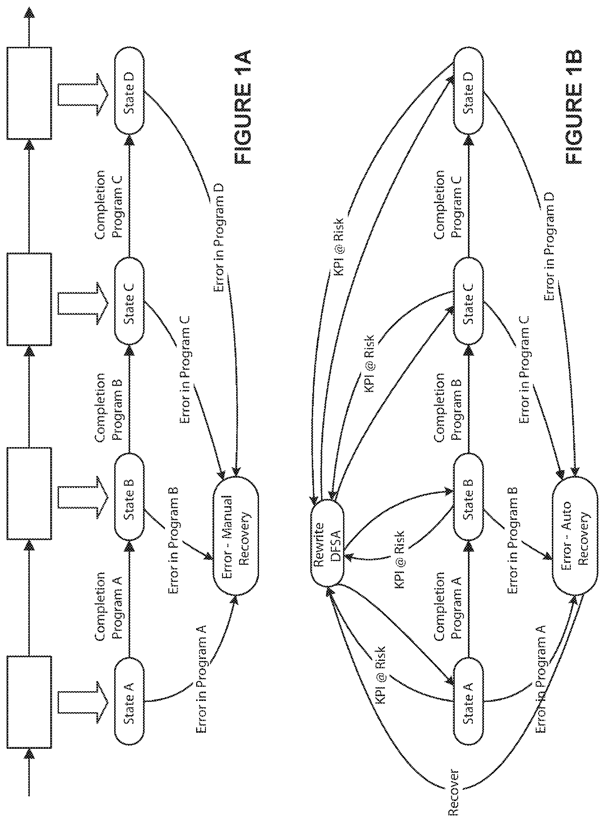
Similarly, once the source of failure has been resolved, traditional process automation systems do not gracefully fall back to the preferred workflows, as their workflow has been changed to accommodate the failure.
This workflow
processing limitation means that the system is not able to temporarily accommodate a failed or failing component and then recover to a preferred mode of
processing once the failure is resolved.
Empty
machine input queues, lack of feedstock, or
machine breakages create stoppages in the workflow that can only be cleared manually.
Traditionally
defined process automation workflows and process automation recipes also are generally not scalable nor are they flexible in what hardware they are performed upon.
Once a workflow has been defined and compiled, the execution of the workflow typically cannot be dynamically re-allocated to a different system while performing the workflow (as opposed to traditional load balancing techniques which run new instances of a workflow on different hardware).
Once resources have been specified in a workflow, additional resources and new or changed process steps typically cannot be automatically removed or added, for example to maintain performance
metrics.
Similarly, a process control
recipe cannot be automatically augmented mid batch to bring a manufacturing process back under control.
This means that once a process falls out of control, there is no automated way to change the controlled process to bring it back into control.
Thus, process automation recipes are often static and typically cannot be changed mid-run to incorporate recipe steps that compensate for an earlier failure, or to select an alternate recipe if a first recipe no longer meets
operational requirements.
Existing traditional process automation systems generally do not operate in real-time, and have trouble operating using dynamically assigned or changing
metrics.
Similarly, they have challenges with providing the forward or predictive management of their workflow's operation in relation to those
metrics.
Specifically, a traditional
process automation system executing predefined workflow instances cannot determine and implement real-time workflow changes to change the workflows based upon externally defined operational metrics.
Existing control systems executing defined workflows often lack a capability to predict bottlenecks in one or more parts of a workflow using metrics that are not hard coded into the workflow (e.g. metrics that are collected and managed outside the normal, predefined
processing of the workflow) and to dynamically rescale or re-define system processing based upon predicted and / or detected processing bottlenecks.
