
Superconducting traveling-wave parametric amplifier

a traveling wave parametric amplifier and superconducting technology, applied in the direction of superconductor devices, instruments, dissimilar materials junction devices, etc., can solve the problems of difficult to achieve compact amplifiers, regimes outside the scope of the present application, and less than ideal traditional semiconductor transistor amplifiers in this environment. achieve the effect of sufficient nonlinear inductance and low input power

Active Publication Date: 2021-05-04
SEEQC INC
View PDF4 Cites 1 Cited by
  • Summary
  • Abstract
  • Description
  • Claims
  • Application Information

AI Technical Summary

Benefits of technology

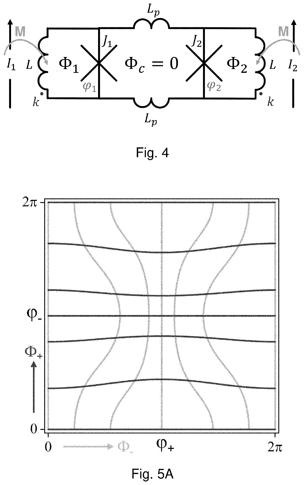
This patent describes a system and method for improving the control and performance of a superconducting traveling-wave parametric amplifier (TWPA) with a designed integrated array of symmetric rf-SQUIDs. The TWPA can match input and output lines with characteristic impedance of about -50 ohms and have a very low input power of -120 dBm or less. It can also be designed to have a high signal power gain of greater than 12 dB and can attenuate the output signal power by more than 20 dB when the pump power is turned off. Additionally, this patent describes a tunable superconducting microwave inductor that can be combined with a fixed capacitor to form a repeated stage in a microwave transmission line, which can function as a TWPA, where the gain and bandwidth of the TWPA can be optimized by tuning the tunable inductors using control currents.

Problems solved by technology

Traditional semiconductor transistor amplifiers are less than ideal in this environment.
However, this regime is outside the scope of the present application, which focuses on small input currents below Ic.
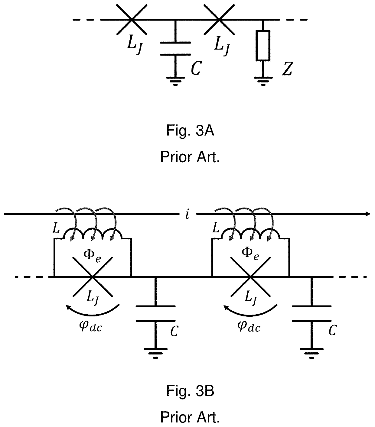
However, this nonlinearity is much weaker than that in a Josephson junction, so that a very long transmission line is needed to obtain sufficient gain, making compact amplifiers very difficult to achieve.
However, the presence of the phase-matching network introduces a tradeoff between bandwidth and gain, as well as increasing the size and complexity of the circuit.
However, with only a single tuning parameter, the various parameters of the TWPA cannot be fully optimized.
The prior art fails to disclose a compact Josephson TWPA that can achieve high gain, low noise, and wide microwave bandwidth with improved control over tuning, compared to the prior art of either FIG. 3A or FIG. 3B.

Method used


Image

  • Superconducting traveling-wave parametric amplifier
  • Superconducting traveling-wave parametric amplifier
  • Superconducting traveling-wave parametric amplifier

Examples


Embodiment Construction

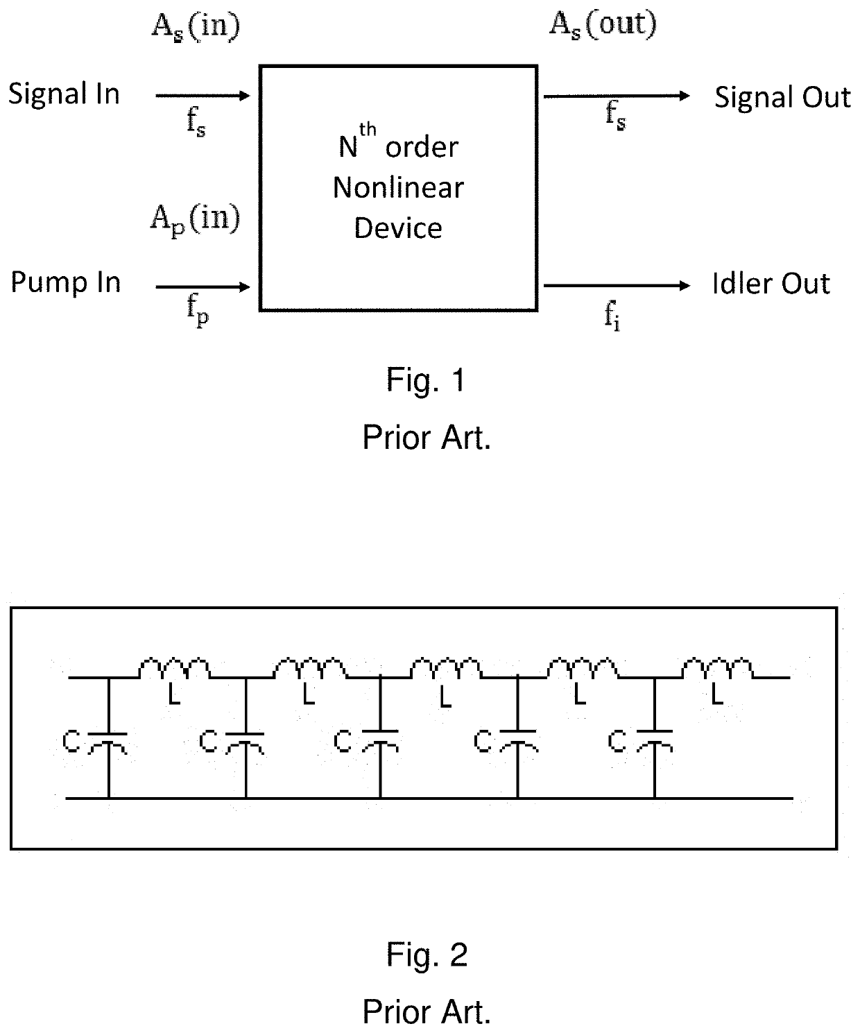
rconducting quantum computing demands non-dissipative, quantum-limited cryogenic amplifiers. In order to improve scalability to many qubits, wide-bandwidth amplifiers are required for readout of multiple qubits which can be sensed with a single amplifier. Josephson Parametric Amplifiers (JPAs) were introduced to meet these needs, and proposed in many different designs. As a parametric amplifier, the JPA transfers power from a strong microwave tone (the pump) to a weak one (the signal), as well as to the idle frequency fi=fp−fs (see FIG. 1). It has the advantage of operating at cryogenic temperatures with very low loss, as well as having the strong intrinsic nonlinearity of the Josephson inductance. While achieving good gain and noise performance, JPAs cannot guarantee a wide instantaneous bandwidth for many-qubit multiplexing, because of a lumped-circuit based design.

[0096]An alternative approach is built around a superconducting transmission line, consisting of superconducting indu...


PUM


Abstract

A system and method are disclosed for a superconducting traveling-wave parametric amplifier (TWPA) with improved control and performance. In a preferred embodiment, the amplifier comprises an integrated array of symmetric rf-SQUIDs in a transmission line structure. A device was fabricated using niobium superconducting integrated circuits, and confirmed predicted performance, with a maximum gain up to 17 dB and a bandwidth of 4 GHz. A similar device can be applied as a low-noise, low-dissipation microwave amplifier for output from a superconducting quantum computer, or as a preamplifier, switch, or frequency converter for a sensitive microwave receiver, or as an output amplifier for a frequency-multiplexed superconducting detector array.

Description

FIELD OF THE INVENTION[0001]The present invention relates to the field of superconducting integrated circuits, especially with application to quantum computing.BACKGROUND OF THE INVENTION[0002]All references cited herein are expressly incorporated herein by reference in their entirety, for all purposes.[0003]There has been much attention recently to the use of superconducting integrated circuits for quantum computing, whereby the quantum bits or qubits may comprise Josephson junctions.[0004]These quantum computing systems are generally designed to operate at very low temperatures much less than 1 K. These systems further require control and output circuitry, which may also comprise superconducting circuits. See, for example, U.S. Pat. Nos. 7,135,701; 7,335,909; 7,002,174; 7,418,283; 6,838,694; 6,495,854; 6,979,836; 6,803,599; 7,253,654; 2005 / 0250651; U.S. Pat. Nos. 6,784,451; 6,459,097; 7,932,514; 7,268,576; 6,627,915; 7,800,395; 7,880,529; 7,605,600; 6,504,172; 8,174,305; 8,102,185...

Claims


Application Information

Patent Timeline
Patent Type & Authority Patents(United States)
IPC IPC(8): H03F19/00G06N10/00H01L39/22H01L39/02H03F7/02H10N60/80
CPCH03F19/00G06N10/00H01L39/025H01L39/223H03F7/02H10N60/12H10N60/805
Inventor MIANO, ALESSANDROMUKHANOV, OLEG A.
Owner SEEQC INC
Learn More