Plasma accelerator

a plasma accelerator and charged particle technology, applied in the direction of excitation process/apparatus, laser details, electrical apparatus, etc., can solve the problems of deteriorating the beam emittance, accelerating charged particles that have accumulated correlated energy, and not uniform acceleration of charged particles

Active Publication Date: 2021-05-18
UNIV OF STRATHCLYDE
View PDF132 Cites 6 Cited by
  • Summary
  • Abstract
  • Description
  • Claims
  • Application Information

AI Technical Summary

Benefits of technology

[0021]The non-uniform acceleration experienced by the first plurality of charged particles due to the non-uniform electric field may be at least partially, fully or over compensated for by the non-uniform acceleration experienced by the first plurality of charged particles due to the local distortion in the non-uniform electric field. The non-uniform acceleration experienced by the first plurality of charged particles due to the local distortion in the non-uniform electric field may narrow the energy distribution of the first plurality of charged particles, for example by one order of magnitude.
[0024]Different particles in the first plurality of charged particles may experience a different acceleration due to the non-uniform electric field. Different particles in the first plurality of charged particles may experience a different acceleration due to the local distortion in the non-uniform electric field. The local distortion required to accelerate the first plurality of charged particles such that the first plurality of charged particles have a particular energy distribution, which may be due to the different accelerations experiences by each particle in the first plurality of charged particles, may be determined by simulation, for example by simulating the properties of the second plurality of charged particles, such as at least one of the spatial distribution, total charge, location, mass and species of the second plurality of charged particles, by controlling the timing of adding, injecting or firing the second plurality of charged particles into the plasma, or by controlling the timing of creating the second plurality of charged particles in the plasma.
[0035]The non-uniform electric field or plasma wave may be created by a laser beam interacting with the plasma, such as a laser pulse, preferably a long-wavelength laser pulse, for example with a wavelength in the range of 1 to 20 μm. The laser pulse may be or comprise an intense laser pulse, for example with peak focus intensity of the order of 1018 W cm−2, such as produced by a typical Ti:Sapphire high-power laser pulse with a central wavelength of ˜800 nm. The wavelength of the laser may be sufficiently long to prevent complete ionisation of the involved plasma species, but may also provide large enough ponderomotive force to expel electrons rapidly out of the laser pulse trajectory and thus generate a plasma wave, preferably a strong plasma wave. Lasers with longer wavelengths may therefore need lower intensity as I∞E2 and may produce correspondingly lower peak values of the electric field E than lasers with shorter wavelengths in order to excite a sufficiently strong plasma wave. The ponderomotive force may scale quadratically with the laser pulse wavelength.

Problems solved by technology

The non-uniform electric fields in a plasma accelerator result in non-uniform acceleration of charged particles.
The accumulated correlated energy spread in the accelerated charged particles is problematic on a number of levels: first, extraction of the charged particles from the plasma accelerator stage, which may require very challenging transport of large divergent beams, can substantially deteriorate the beam emittance due to chromatic effects and non-matched transverse forces.

Method used


Image

  • Plasma accelerator
  • Plasma accelerator
  • Plasma accelerator

Examples


Embodiment Construction

[0075]Throughout the following description, identical reference numerals will be used to identify identical parts.

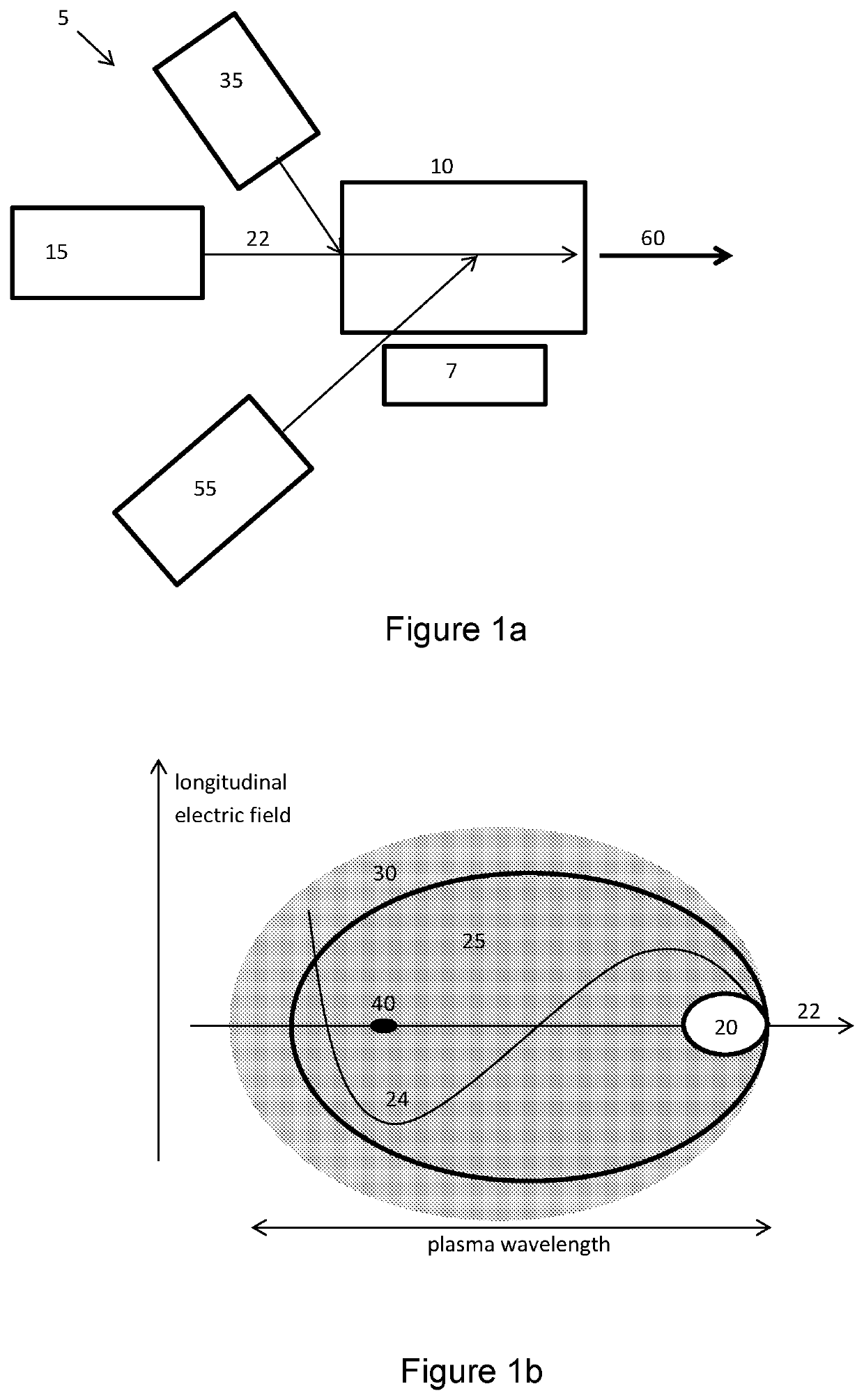
[0076]Embodiments of the present invention relate to plasma-based accelerators. Plasma based accelerators can provide very high energy gains and can allow an increase of electron 5D-brightness by orders of magnitude. A plasma accelerator suitable for use with the present invention is shown in FIG. 1a. The accelerator 5 comprises a chamber 10 for containing the plasma. A medium from which the plasma is formed is present in the chamber 10. A plasma generator 7, such as a heater or an electromagnetic field generator, creates and maintains the plasma in the chamber 10. The accelerator 5 comprises one or more plasma drivers 15, such as lasers, electron beam generators, proton beam generators or the like. The plasma drivers 15 are operable to provide an excitation beam 20 along a beam axis 22 through the medium in the chamber 10, thereby forming a plasma wave within the plasma...


PUM


Abstract

A method of accelerating charged particles in a plasma and an associated plasma accelerator and electromagnetic radiation source, the method including creating a region of non-uniform electric field within the plasma which propagates through the plasma; using the non-uniform electric field to accelerate a first plurality of charged particles in the direction of propagation of the region of non-uniform electric field; and once the accelerating first plurality of charged particles have propagated part-way through the plasma: adding a second plurality of charged particles to the plasma, such that the second plurality of charged particles propagates through the plasma, the second plurality of charged particles create a local distortion in the non-uniform electric field experienced by the accelerating first plurality of charged particles, and the local distortion in the non-uniform electric field propagates through the plasma with the accelerating first plurality of charged particles; and the method also including using the local distortion in the non-uniform electric field to accelerate the first plurality of charged particles in the direction of propagation of the region of non-uniform electric field.

Description

CROSS REFERENCE TO RELATED APPLICATIONS[0001]This application is a National Stage Application, filed under 35 U.S.C. § 371, of International Application No. PCT / GB2017 / 052942, filed Sep. 29, 2017, which international application claims priority to United Kingdom Application No. 1617173.8, filed Oct. 10, 2016; the contents of both of which as are hereby incorporated by reference in their entirety.BACKGROUNDRelated Field[0002]The present invention relates to a method for accelerating charged particles with a plasma accelerator, such as a method that accelerates electrons and improves the energy spread of the accelerated electrons, which, optionally but not essentially, may be used to generate electrons for a free electron laser (FEL) and other high intensity light sources. The present invention also relates to an associated plasma accelerator, and advanced light sources based on the accelerated charged particles.Description of Related Art[0003]Acceleration of electrons in laser, elect...

Claims


Application Information

Patent Timeline
Patent Type & Authority Patents(United States)
IPC IPC(8): H05H1/54H05H15/00H01S3/09H05H1/46
CPCH05H1/54H01S3/0903H05H1/46H05H15/00
Inventor HIDDING, BERNHARDMANAHAN, GRACEHABIB, FAHIM AHMADSCHERKL, PAUL
Owner UNIV OF STRATHCLYDE
Why Eureka
Try Eureka