
Internal combustion engine control method and internal combustion engine control device

Active Publication Date: 2021-08-17
NISSAN MOTOR CO LTD
View PDF16 Cites 1 Cited by
  • Summary
  • Abstract
  • Description
  • Claims
  • Application Information

AI Technical Summary

Benefits of technology

The patent is about a system that collects fine particles from the exhaust gas of an engine. When the collection reaches a certain level, the system needs to regenerate by burning the collected particles and removing them. This results in heated exhaust gas that may affect the operation of the system. The objective of the patent is to prevent the refrigerant in the system from boiling even if the regeneration process occurs.

Problems solved by technology

As a result, in a configuration in which the exhaust gas flows into the exhaust heat recovery device after passing the PF, when regeneration is carried out, the amount of recovered heat in the exhaust heat recovery device increases; thus, the refrigerant easily boils in the exhaust heat recovery device.
Thus, in the control disclosed in the above-described document, there is the risk that the refrigerant will boil when regeneration is performed.

Method used


Image

  • Internal combustion engine control method and internal combustion engine control device
  • Internal combustion engine control method and internal combustion engine control device
  • Internal combustion engine control method and internal combustion engine control device

Examples


first embodiment

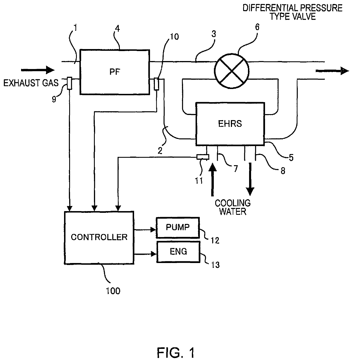
[0019]FIG. 1 is a schematic diagram of a system to which the first embodiment is applied. A filter 4 is disposed in an exhaust passage 1. The exhaust passage 1 branches, downstream of the filter 4, into a main passage 2 provided with an exhaust heat recovery device 5 serving as an exhaust gas temperature variation factor unit, and a bypass passage 3, which bypasses the exhaust heat recovery device 5. A differential pressure type valve 6 is disposed in the bypass passage 3.

[0020]The filter 4 has a function of collecting particulate matter included in exhaust gas. Specifically, it is a GPF when an internal combustion engine 13 is a gasoline engine, and a DPF in the case of a diesel engine.

[0021]A first pressure sensor 9 is disposed on the upstream side of the filter 4 of the exhaust passage 1, and a second pressure sensor 10 is disposed on the downstream side thereof. Detected values of the first pressure sensor 9 and the second pressure sensor 10 are read by a controller 100 serving ...

second embodiment

[0064]The second embodiment will be described. The difference from the first embodiment lies in the content of the boiling avoidance process. In the first embodiment, the prohibition of forced regeneration acts as the boiling avoidance process, but in the second embodiment, in addition to the prohibition of forced regeneration, an increased refrigerant flow rate is also used. Hereinafter, differences from the first embodiment will be mainly described.

[0065]FIG. 6 is a flowchart illustrating a control routine executed by the controller 100. Since Steps S200-S213 are the same as Steps S100-S113 of FIG. 5, their description will be omitted.

[0066]In Step S214, the controller 100 increases the refrigerant flow rate and ends the current routine. The amount of increase is set in advance on the basis of suitability, or the like. When the refrigerant flow rate is increased, the refrigerant temperature at the outlet of the exhaust heat recovery device 5 decreases even if the amount of recover...

third embodiment

[0069]The third embodiment will now be described. In the control described in the first and second embodiments, it is determined whether the refrigerant would boil before carrying out forced regeneration, and the forced regeneration is prohibited if there is a risk of boiling. In contrast, the control of the present embodiment is carried out if regeneration were to start at an unintended timing. A case in which regeneration starts at an unintended timing is, for example, a case in which the filter 4 is a GPF, and the engine rotation speed increases as a result of the driver depressing the accelerator pedal to accelerate, thereby starting regeneration.

[0070]FIG. 7 is a flowchart illustrating a control routine executed by the controller 100.

[0071]In Step S300, the controller 100 determines whether the difference between the refrigerant temperature at the inlet and the refrigerant temperature at the outlet of the exhaust heat recovery device 5 (hereinafter also referred to as refrigera...


PUM


Abstract

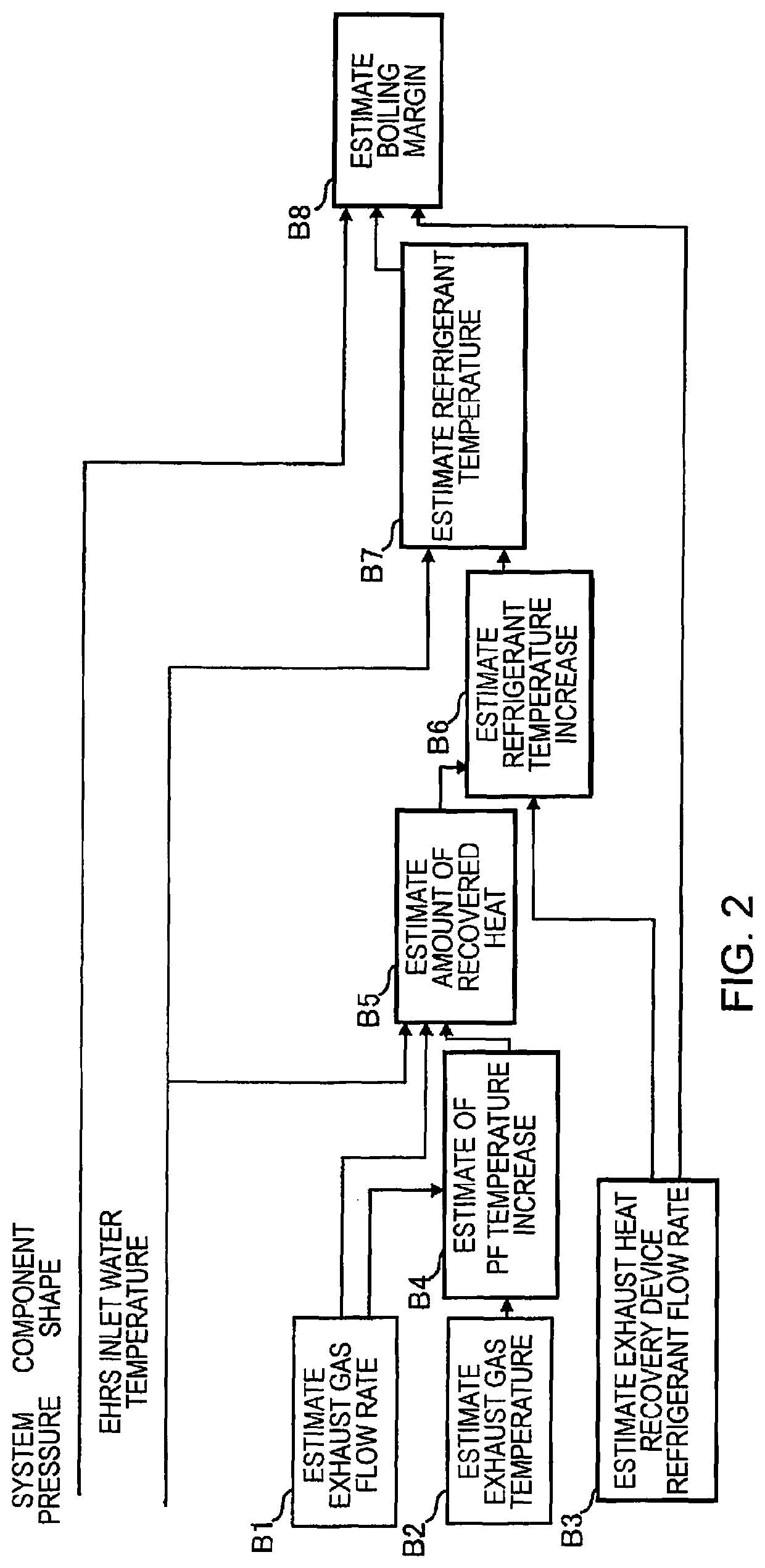
An internal combustion engine control method controls an internal combustion engine equipped with an exhaust gas temperature variation factor unit that varies the temperature of an exhaust gas of the internal combustion engine, an exhaust heat recovery device disposed in an exhaust passage downstream of the exhaust gas temperature variation factor unit and that recovers the heat from the exhaust gas into a refrigerant that cools the internal combustion engine, and a refrigerant flow rate adjustment unit that adjusts a flow rate of the refrigerant that passes through the exhaust heat recovery device. The internal combustion engine control method estimates a boiling margin, which is a parameter related to a thermal margin when the refrigerant boils in the exhaust heat recovery device, and determines whether to execute a boiling avoidance process in accordance with the boiling margin.

Description

CROSS-REFERENCE TO RELATED APPLICATIONS[0001]This application is a U.S. national stage application of International Application No. PCT / JP2018 / 010892, filed on Mar. 19, 2018.BACKGROUNDTechnical Field[0002]The present invention relates to control of an internal combustion engine.Background Information[0003]An exhaust gas recovery system that recovers the heat from exhaust gas (hereinafter also referred to as exhaust heat) into a refrigerant for cooling the engine for the purpose of improving performance of a vehicle heater and increasing the temperature of cooling water at an early stage at the time of starting a cooler is known. As a specific configuration, a configuration in which an exhaust heat recovery device is provided in an exhaust passage of an engine, and heat exchange is carried out between the exhaust gas and the refrigerant in this exhaust heat recovery device, is known.[0004]When the exhaust heat recovery system described above is provided, it becomes necessary to preve...

Claims


Application Information

Patent Timeline
IPC IPC(8): F01N9/00F02D41/02F01N3/023F01P3/20F01N5/02
CPCF01N9/002F02D41/029F01N3/023F01N5/02F01N2240/02F01N2240/20F01N2560/06F01N2560/08F01P3/20F01P2060/16Y02T10/12F01N3/0205F01P3/12F01N2410/02Y02T10/40
Inventor FUKAMI, TORUKAWAHARA, KENTAROIRIBE, YOSHIFUMI
Owner NISSAN MOTOR CO LTD
Learn More