Determination of an interrupted motor phase of an electric motor

a technology of interrupted motor and electric motor, which is applied in the direction of electronic commutators, dynamo-electric converter control, instruments, etc., can solve the problems of unnecessarily high phase current in the other phases or windings of the electric motor, and one of the phases of the electric motor may be interrupted or decoupled, so as to avoid overheating or overloading, the effect of preventing damag

Active Publication Date: 2021-09-14
ROBERT BOSCH GMBH
View PDF3 Cites 0 Cited by
  • Summary
  • Abstract
  • Description
  • Claims
  • Application Information

AI Technical Summary

Benefits of technology

[0014]In this case, the induced voltage can be monitored without additional sensors. The outer conductors already connected to the electric motor can be used in the motor controller to measure the induced voltages. The voltages can preferably be measured in the respective phases or outer conductors while the latter are briefly deenergized or do not have a voltage applied to them. As a result, the frequencies and / or the level of the induced voltages in the windings of the electric motor can be monitored in parallel with operation of the electric motor. It is therefore possible to avoid an unnecessarily high phase current during operation of the electric motor.
[0020]According to one embodiment, the electric motor is at least temporarily deactivated or is operated with a reduced current if an interrupted motor phase is determined. Determining an interrupted phase makes it possible to carry out measures to prevent damage. This can be implemented, for example, by coupling the measurement of the induced voltages to the motor controller. In particular, this makes it possible to implement self-protection for the electric motor, which avoids overheating or overloading. In this case, there is a minimum need to change the existing components for operating the electric motor since no additional components are required.
[0021]According to a further embodiment, the control unit is in the form of at least one BEMF comparator or in the form of an electric motor controller with at least one BEMF comparator. The induced voltage is measured in the form of a signal from the BEMF comparator. The determined signals of the outer conductors are compared with one another. This makes it possible to integrate or implement the method directly in an electric motor controller without the need for additional sensors or electronic connections. The at least one BEMF comparator can preferably be connected to a phase or outer conductor of the electric motor via at least one resistor in order to carry out a voltage measurement.

Problems solved by technology

As a result of a fault, one of the phases of the electric motor may be interrupted or decoupled from the motor controller.
However, an interruption of a phase may result in an unnecessarily high phase current in the other phases or windings of the electric motor.

Method used


Image

  • Determination of an interrupted motor phase of an electric motor
  • Determination of an interrupted motor phase of an electric motor
  • Determination of an interrupted motor phase of an electric motor

Examples


Embodiment Construction

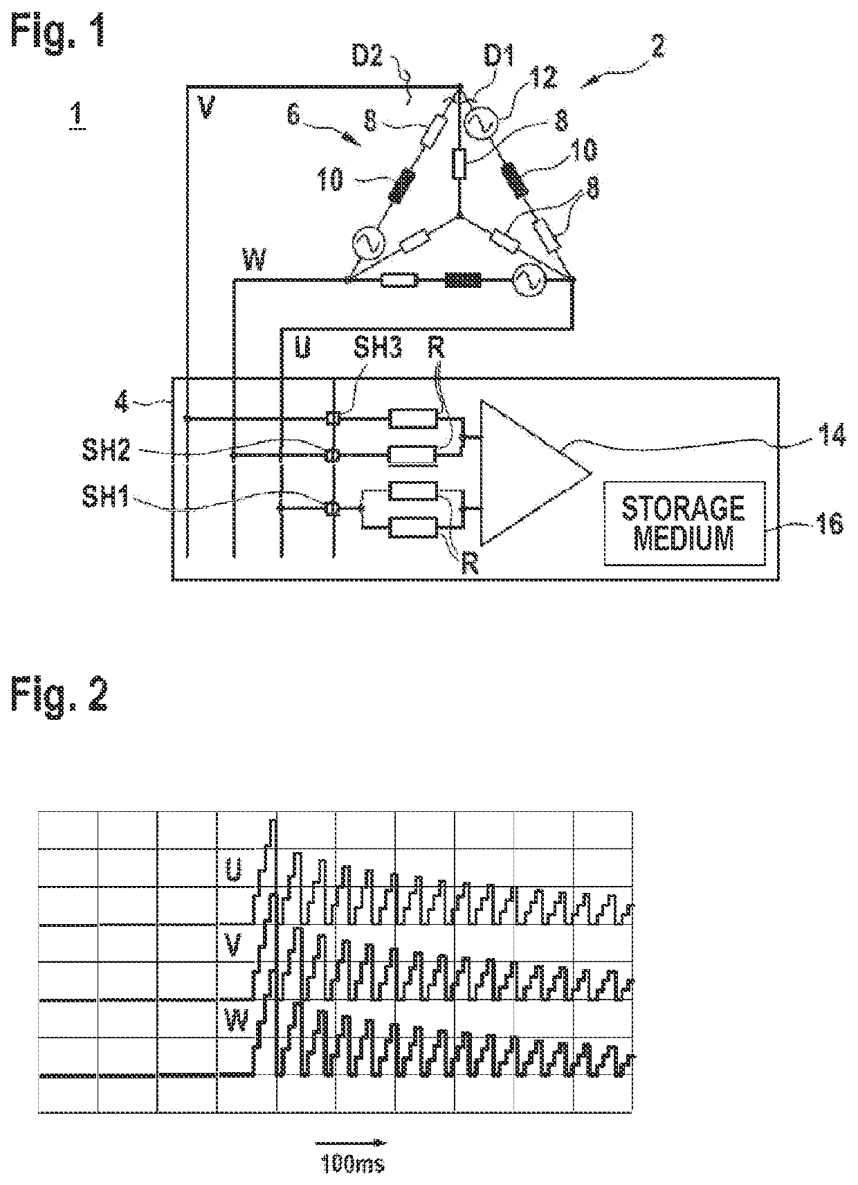
[0036]FIG. 1 illustrates a schematic circuit diagram of an arrangement 1 having an electric motor 2 and a connected control unit 4 according to one embodiment.

[0037]In particular, the circuit diagram is used to illustrate a method for determining an interrupted motor phase U, V, W of the electric motor 2 having three windings 6 by means of the control unit 4.

[0038]An equivalent circuit diagram for the electric motor 2 is illustrated. Each winding 6 can be described here as a combination of a resistor 8 and an inductance 10. The respective voltage sources 12 (BEMF) in the windings 6 are likewise illustrated in the form of a sinusoidal profile for the sake of completeness.

[0039]The outer conductors U, V, W or the motor phases are not represented in the control unit 4 by circuit breakers. The control unit 4 is implemented at least once and electrically connects the respective outer conductors U, V, W to the comparator 14 via connection points SH1, SH2, SH3. One control unit 4 is illust...


PUM


Abstract

A method for determining an interrupted motor phase of an electric motor having at least three windings by means of a control unit is disclosed, wherein voltages induced in the windings are determined on outer conductors of the electric motor by means of at least one measuring unit, wherein the measuring unit is connected to at least one outer conductor of the electric motor via at least one resistor, the induced voltages of the outer conductors of the electric motor are compared with one another, and an interrupted motor phase is registered if the induced voltage differs or if a frequency of the induced voltage differs. A control unit, a computer program and a machine-readable storage medium are also disclosed.

Description

BACKGROUND OF THE INVENTION[0001]The invention relates to a method for determining an interrupted motor phase of an electric motor having at least three windings, to a control unit, to a computer program and to a machine-readable storage medium.[0002]Internal combustion engines are usually used as drive motors in vehicles. The internal combustion engines can be in the form of gasoline engines or diesel engines, for example. As a result of the combustion of the fuel, thermal energy is produced during operation of the internal combustion engine and is dissipated from the engine block via a cooling circuit. The cooling circuit is guided through a heat sink or a radiator which is actively cooled by means of at least one fan. Fans are also used in other vehicles, for example electric vehicles and hybrid vehicles, for example to cool batteries and power electronics.[0003]Such a fan is driven, for example, by an electric motor having a three-phase design. As a result of a fault, one of the...

Claims


Application Information

Patent Timeline
Patent Type & Authority Patents(United States)
IPC IPC(8): H02K29/06H02P6/18H02P29/024H02P8/36
CPCH02P6/186H02P8/36H02P29/025H02P29/0241G01R31/343H02H7/09H02P29/028H02P29/0243H02P29/032H02P6/182
Inventor DENZ, DOMINIKFKAIER, HAITHEM
Owner ROBERT BOSCH GMBH
Why Eureka
Try Eureka