

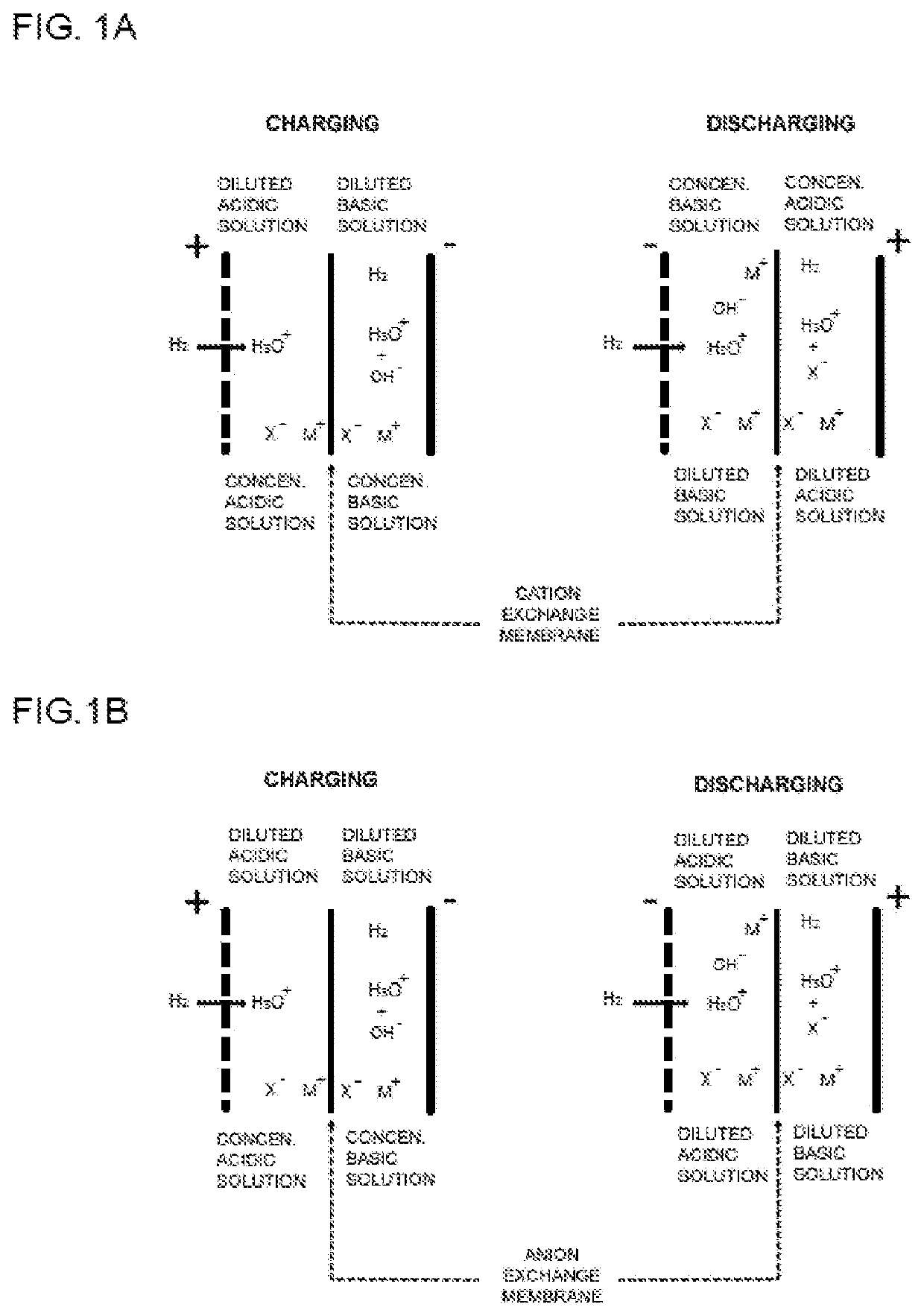
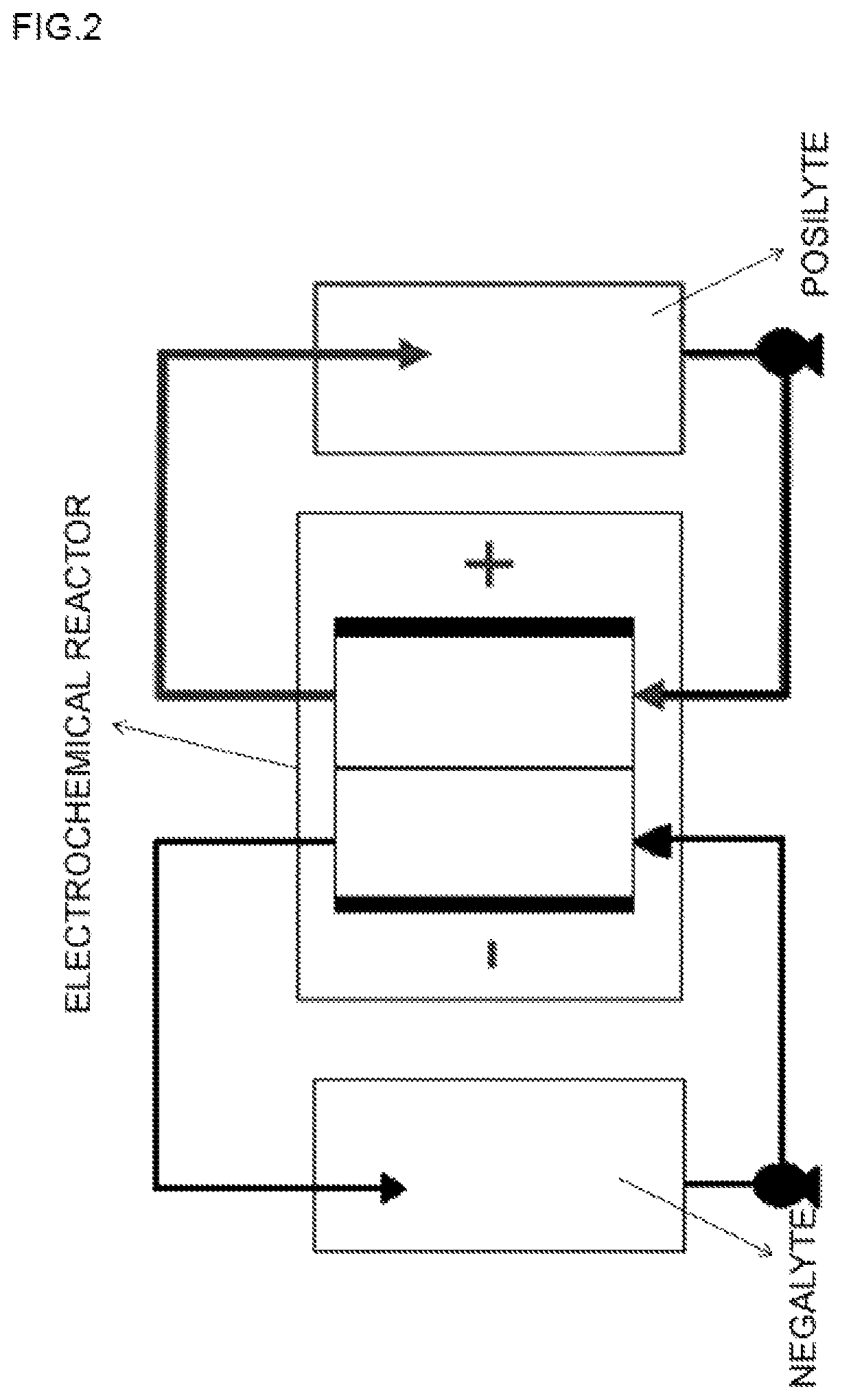
Acid-based electrochemical flow battery
a flow battery and acid-based technology, applied in the field of acid-based electrochemical flow batteries, to achieve the effects of high faradaic efficiency of the two reactions, high reversibility of the process, and virtually 100%
- Summary
- Abstract
- Description
- Claims
- Application Information
AI Technical Summary
Benefits of technology
Problems solved by technology
Method used
Image

Examples
example 1
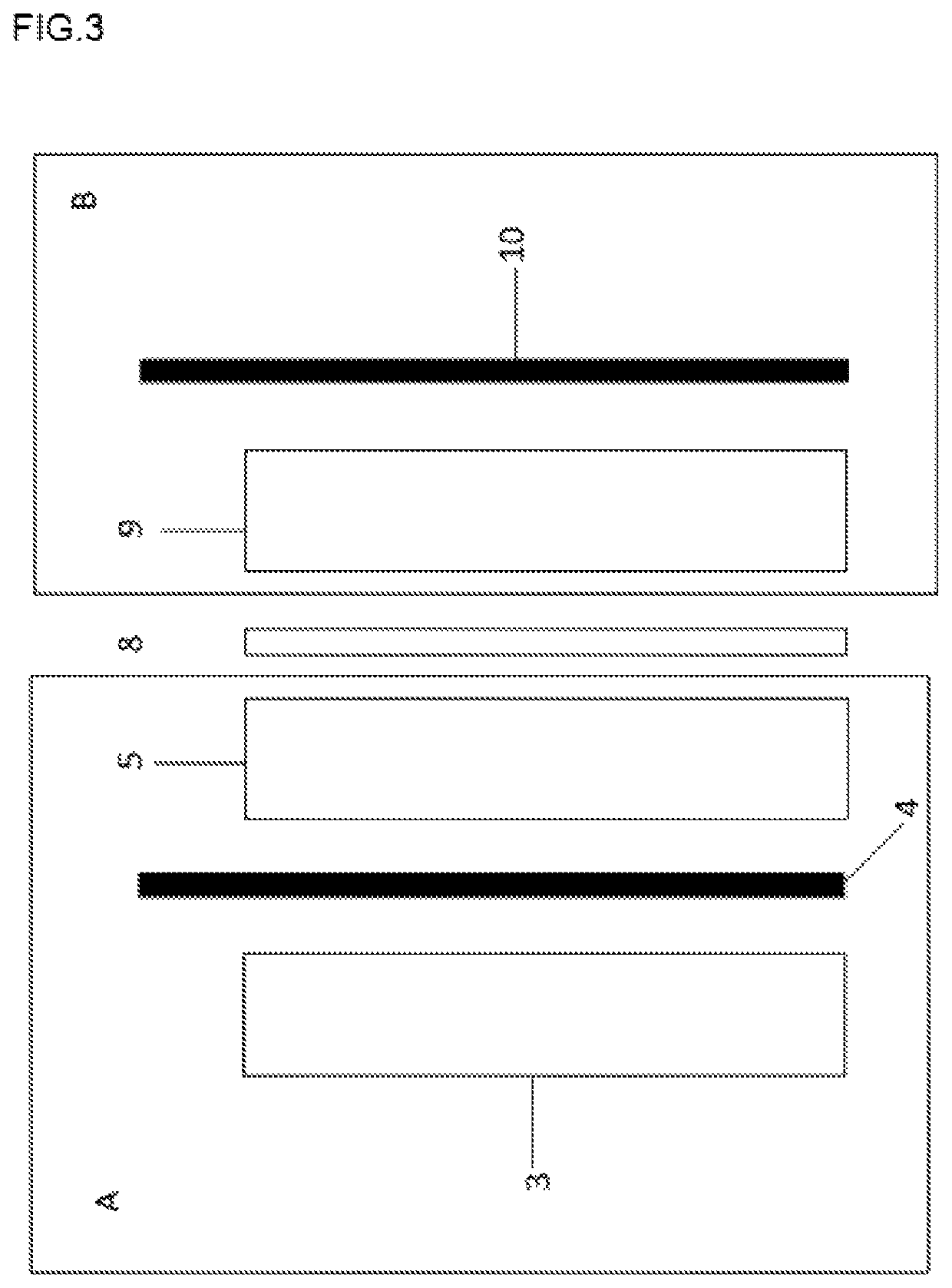
[0043]In this example, a battery charging process is performed using 1 M NaOH and 1 M HCl as the posilyte and negalyte, respectively. Both solutions contain 2 M NaCl as the supporting electrolyte. The volume of the negalyte and posilyte is 50 ml. The electrode structure used is made up of a diffusion electrode formed by 20% wet-proofed Toray Paper TGPH-90 on which a microporous layer of a mixture of PTFE and Vulcan XC72 at a 60 / 40 weight ratio and a coating of 2.5 (mg Vulcan XC72) cm−2 is deposited. A catalytic layer is constructed on this layer using Pt / C at 30% by weight as an electrocatalyst and Nafion as a binder at a 60 / 40 ratio, the final catalytic coating being 1 (mg Pt) cm−2. This diffusion electrode is used in the oxidation reaction of hydrogen. Similarly, a platinized titanium electrode is used in the hydrogen formation reaction. Finally, the electrode geometric area of this system is 4 cm2.
[0044]The polarization curve (FIG. 6) of the system was first obtained, and then ch...
example 2
[0045]In this example, a battery discharging process is performed using 1 M NaOH and 1 M HCl as the negalyte and posilyte, respectively. Both solutions contain 2 M NaCl as the supporting electrolyte. The volume of the negalyte and posilyte is 50 mL. The electrodes described above were used as electrodes.
[0046]The polarization curve and power curve (FIG. 8) were first obtained, and then discharging was performed at a constant current density of 25 mA cm−2 for 7200 seconds. FIG. 9 shows the evolution of the potential difference over time.
PUM
| Property | Measurement | Unit |
|---|---|---|
| Faradaic efficiency | aaaaa | aaaaa |
| current density | aaaaa | aaaaa |
| current density | aaaaa | aaaaa |
Abstract
Description
Claims
Application Information