Dental furnace

a technology of dental furnace and furnace, which is applied in the field of dental furnace, can solve the problems of conventional furnaces, inability to achieve uniform firing results, and inability to ensure predetermined temperature increase per time unit, so as to achieve fast and uniform firing of ceramic elements, reduce cooling time, and improve the effect of drying

Active Publication Date: 2021-10-26
VITA ZAHNFABRIK H RAUTER GMBH & CO KG
View PDF17 Cites 0 Cited by
  • Summary
  • Abstract
  • Description
  • Claims
  • Application Information

AI Technical Summary

Benefits of technology

[0013]By using these quick-response heating elements, the preheating times of the ceramic elements to be fired can be considerably reduced. The additional IR radiation portion in the wavelength range below approximately 2 μm allows for a larger penetration depth into the dental-ceramic compound. The resultant heating inside the dental-ceramic compound or in its deeper layers leads in a quicker evaporation of the existing liquid substance. This takes place immediately before the heating or firing operation such that the outer layer of the dental-ceramic compound is not already closed by fusion and thus the existing liquid substance can easily escape. Thus despite a shorter preheating phase there is no risk that the ceramic material flakes off a possibly existing supporting structure, which is typically caused by evaporation of liquid in the lower layers of the ceramic material after the surface of the ceramic material has been closed. Due to the use of these quick-response heating elements in the infrared range of approximately 0.8-5 μm according to the disclosure, thus considerably shorter firing times can be realized. Furthermore, preheating is required for a considerably shorter period of time. Thereby, the energy consumption is considerably reduced.
[0018]For further improving the firing quality and for reducing the firing times, it is preferred that at least one reflection element is arranged in the firing chamber. By means of the reflector element the infrared radiation emitted by the at least one quick-response heating element is directed towards the ceramic element to be fired. Preferably, the at least one heating element, which is in particular of a cylindrical configuration, is at least partially surrounded by the reflector element. In particular, the cross-section of the reflector element is parabolic or approximately parabolic, if possible, to ensure in an effective manner a corresponding reflection / deflection of the radiation emitted by the at least one quick-response heating element towards the ceramic element. Here, it is particularly preferred that the at least one reflector element is configured as an elongate body. This body preferably extends over the overall heating length of the respective heating element which has a parabolic, cylindrical or similar configuration, for example. Thereby, the effectiveness of the dental furnace according to the disclosure can be considerably increased.
[0020]According to a particularly preferred aspect of the disclosure, a receiving element, such as a firing table, for receiving a ceramic element is provided in the firing chamber. Here, the receiving element is made from a radiation-absorbing material or comprises a radiation-absorbing material. In particular, the receiving element comprises a material which absorbs infrared radiation to a large extent such that the receiving element, in particular in connection with the quick-response active heating element(s), serves as an additional (passive) heating element. The ceramic element is additionally heated from below by heat radiation and from inside by heat conduction by this passive heating element. This leads to a uniform distribution of the heat over the overall ceramic element resulting in an improvement of the quality, as well as a shortened firing time and thus saving of energy. It is particularly preferred that the receiving element is made of a dark, in particular black, material for better radiation absorption and thus quicker heating. Particularly preferred is the use of silicon carbide, wherein the receiving element preferably comprises silicon carbide and is in particular made from silicon carbide.
[0021]For avoiding heat dissipation from the receiving element into a chamber wall, into a chamber bottom or the like, the receiving element preferably comprises spacers for insulation purposes such that the contact surface between the receiving element and the corresponding chamber bottom is as small as possible.
[0023]The use according to the disclosure of the quick-response infrared heating elements in the range of approximately 0.8-5 μm does not only offer the advantage that the IR radiation deeply penetrates the ceramic element to be fired and causes good drying, but also that a quick and uniform firing of the ceramic element is performed. In particular, the furnace according to the disclosure requires no or only little preheating. Furthermore, the cooling times are considerably shorter than in the case of conventional furnaces such that the furnace is ready for the next firing operation after a short time.
[0024]In addition, the use of the quick-response infrared heating elements in the range of approximately 0.8-5 μm does not only result in shorter operating times but also in constant, very consistent and high-quality firing results. Furthermore, an exacter control of the firing process is possible. This is in particular advantageous when modern materials with very small uniform particle sizes (nanoparticles) are used.

Problems solved by technology

Without such preheating, uniform firing results cannot be achieved and also the predetermined temperature increase per time unit is not ensured.
Conventional furnaces are therefore disadvantageous in that they have to be preheated or kept at the operational temperature.
This results in a considerable energy consumption.
Furthermore, the cycle time, i.e. the time from preheating to completion of the ceramic element to be fired, is very long.
Conventional furnaces can meet these demands only to a limited extent.
Furthermore, preheating is required for a considerably shorter period of time.
Consequently, an undesired heating of the surroundings of the furnace does not takes place.

Method used


Image

  • Dental furnace

Examples


Embodiment Construction

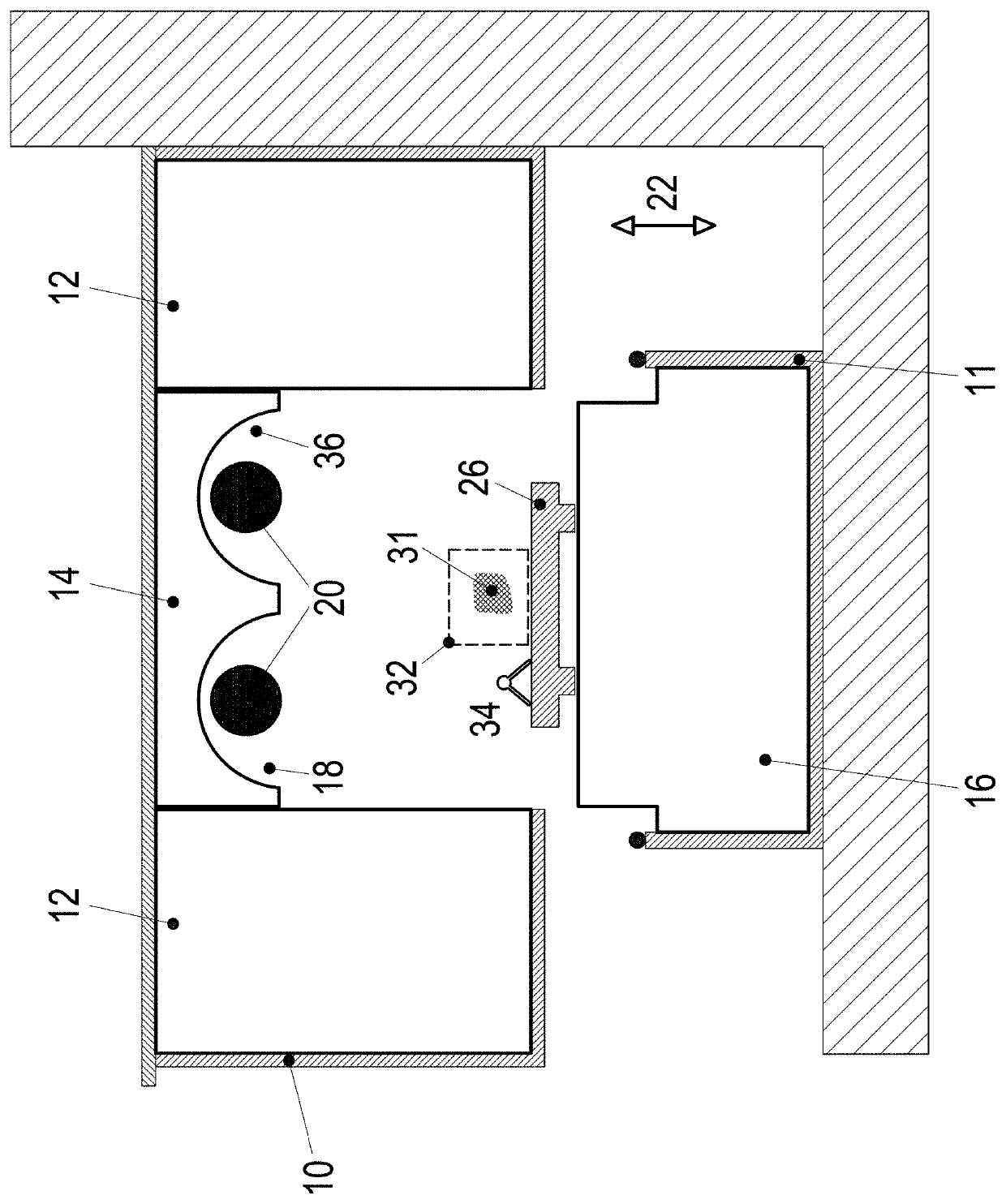
[0027]The schematically illustrated and strongly simplified furnace comprises a firing chamber. The latter is defined by thermally insulated chamber walls, side wall 12, top 14 and bottom 16. The thermal insulation of the top 14 comprises two parabolic recesses 18 in the longitudinal direction, i.e. perpendicular to the drawing level. In these recesses a cylindrical heating element 20 also extending in the longitudinal direction perpendicularly to the drawing level is respectively arranged. The heating device may respectively comprise a plurality of heating elements 20. In particular, per heating element 20 at least one IR emitter is provided. Depending on the installation position, the orientation of the heating elements 20 may also be horizontal, transverse or the like, for example.

[0028]The housing bottom 11 and the firing chamber are adapted to be vertically displaced relative to each other in the direction of an arrow 22 for opening and closing the firing chamber. The housing b...


PUM

PropertyMeasurementUnit
wavelength rangeaaaaaaaaaa
temperaturesaaaaaaaaaa
wavelengthaaaaaaaaaa

Abstract

A dental furnace for firing dental-ceramic compounds comprises a firing chamber for receiving ceramic elements to be fired. Further, a heating device for heating and firing the ceramic element is provided. The heating device comprises at least one heating element for producing IR radiation in the range of 0.8-5 μm.

Description

BACKGROUND1. Field of the Disclosure[0001]The disclosure relates to a dental furnace for firing dental-ceramic compounds as well as for firing dental-ceramic compounds onto dental alloys, zirconium oxide and / or other ceramic materials in connection with a liquid substance (mixing liquid).2. Discussion of the Background Art[0002]Conventional furnaces for dental-ceramic compounds comprise, at least partially, a firing chamber housing adapted to be evacuated. This firing chamber housing is provided with a thermally insulating lining. Prior to firing dental-ceramic compounds, conventional furnaces must be preheated over an extended period of time for setting the thermally insulating lining to a basic temperature. Without such preheating, uniform firing results cannot be achieved and also the predetermined temperature increase per time unit is not ensured. In conventional furnaces, heating elements having resistance wires, in particular of an iron-chromium-aluminum alloy, inserted into a...

Claims


Application Information

Patent Timeline
Patent Type & Authority Patents(United States)
IPC IPC(8): F27B17/02A61C13/20F27D1/00F27D99/00F27B5/14
CPCA61C13/20F27B17/025F27D1/0036F27D99/0006F27B5/14F27D2099/0011F27B17/00
Inventor BAHOLZER, THOMAS
Owner VITA ZAHNFABRIK H RAUTER GMBH & CO KG
Why Eureka
Try Eureka