System for power recovery from quench and dilution vapor streams

a technology of vapor stream and power recovery system, which is applied in the field of vapor streams, can solve the problems of limited hot catalyst flow, limited hot catalyst circulation rate, and low temperature of diluent or quench vapor stream, and achieve the effects of increasing catalyst circulation, reducing riser heat input, and increasing catalyst circulation

Active Publication Date: 2021-12-07
UOP LLC
View PDF59 Cites 0 Cited by
  • Summary
  • Abstract
  • Description
  • Claims
  • Application Information

AI Technical Summary

Benefits of technology

[0012]In the case of an FCC unit, having a dilution stream nearer its dew point will reduce the riser heat input allowing more heat to be added by increased catalyst circulation and providing more selective cracking to desired LPG and naphtha components. In the case of a hydroprocessing reactor, less hydrogen will be required in the quench vapor streams, resulting in lower energy use in the recycle gas compressor, and / or allowing more hydrogen to be injected into the inlet of the reactor—promoting longer first bed catalyst life and higher hydrogenation in each bed but the last. At fixed hydrogen flow, the cooler hydrogen allows more hydrocarbon charge to the reactor as more of the heat of reaction is cooled with the same flow of now cooler hydrogen. Additionally, in addition to the foregoing benefits, the turbines convert the removed energy into electrical energy to be utilized elsewhere. Thus, the turbines provide an additional advantage over the control valves currently used with the dilution and quench streams.
[0013]Therefore, in at least one aspect, the present invention may be characterized, as providing a process for reducing pressure of a vapor stream used for reducing a temperature, a heat load, or a hydrocarbon partial pressure in a reactor by: reducing a pressure of a vapor stream with a turbine to provide a lower pressure vapor stream; rotating a turbine wheel within the turbine; injecting the lower pressure vapor stream into a reactor in order to reduce a temperature or total heat injection to the reactor or reduce a partial pressure of a hydrocarbon vapor in the reactor.

Problems solved by technology

In reactors, the lowest temperature of the diluent or quench vapor streams is occasionally limited by the dew point of the vapor stream.
The flow of hot catalyst added to the reactor is limited by maximum reactor temperatures promoting thermal cracking.
Due to the usually high pressure drop from steam supply to the reactor riser, the steam enters with a large amount of superheat unnecessarily producing a reactor temperature higher than what might be possible with a steam source with less superheat.
This limits the hot catalyst circulation rate and tends to give more unwanted thermal cracking versus catalytic cracking.
The hydroprocessing unit throughput is often limited by flow of quench hydrogen to keep the reactor catalyst bed temperatures in a safe range.
While these conventional systems are presumably effective for their intended purposes, the control valves result in a loss of mechanical energy.
Specifically, since the energy removed, via the pressure reduction, is dissipated without recovery by the control valve, the energy is lost.
Additionally, because the energy removed often is a result of energy added to the system, the lost energy can represent a higher operating cost.
This lost energy results in minimal temperature reduction versus the pressure reduction via an adiabatic pressure reduction across the control valve.

Method used


Image

  • System for power recovery from quench and dilution vapor streams
  • System for power recovery from quench and dilution vapor streams
  • System for power recovery from quench and dilution vapor streams

Examples


examples

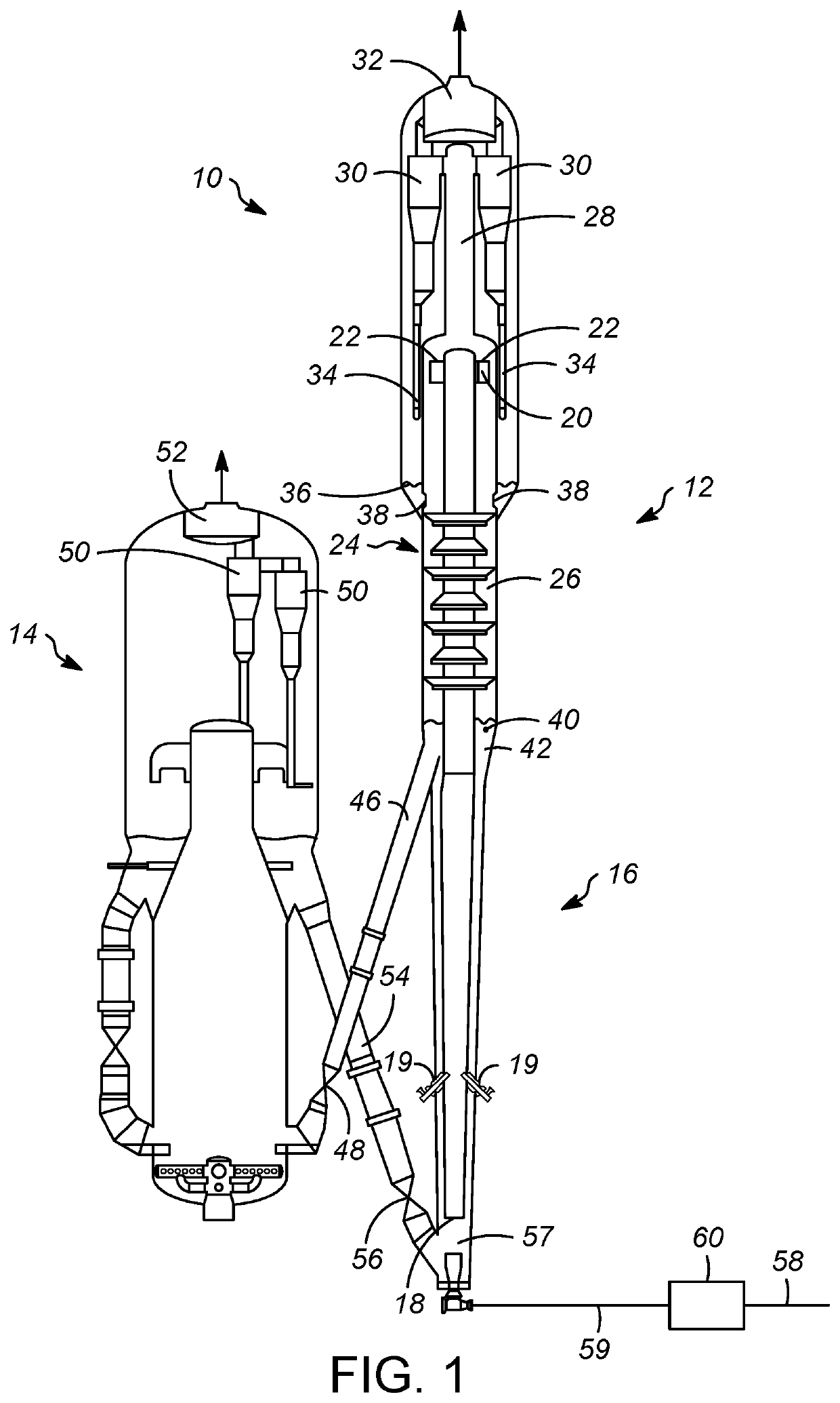
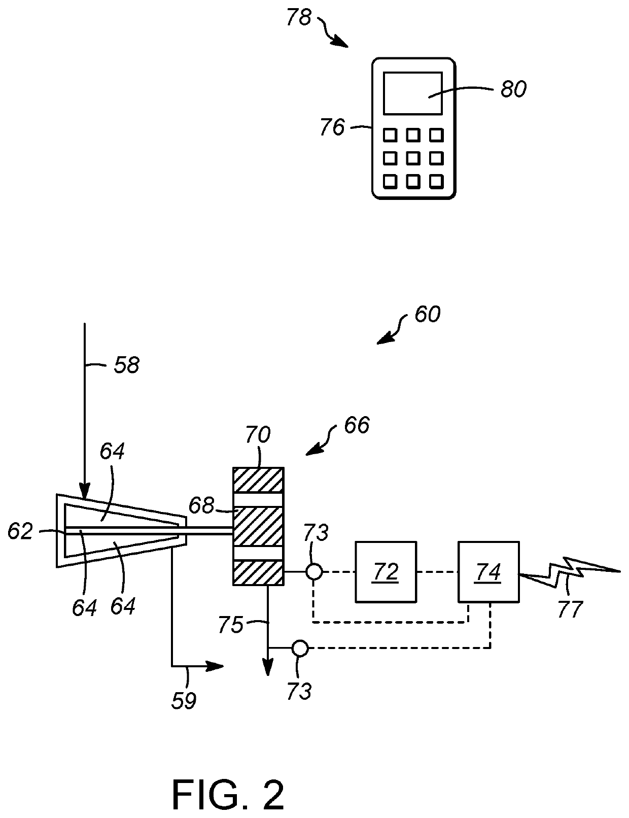
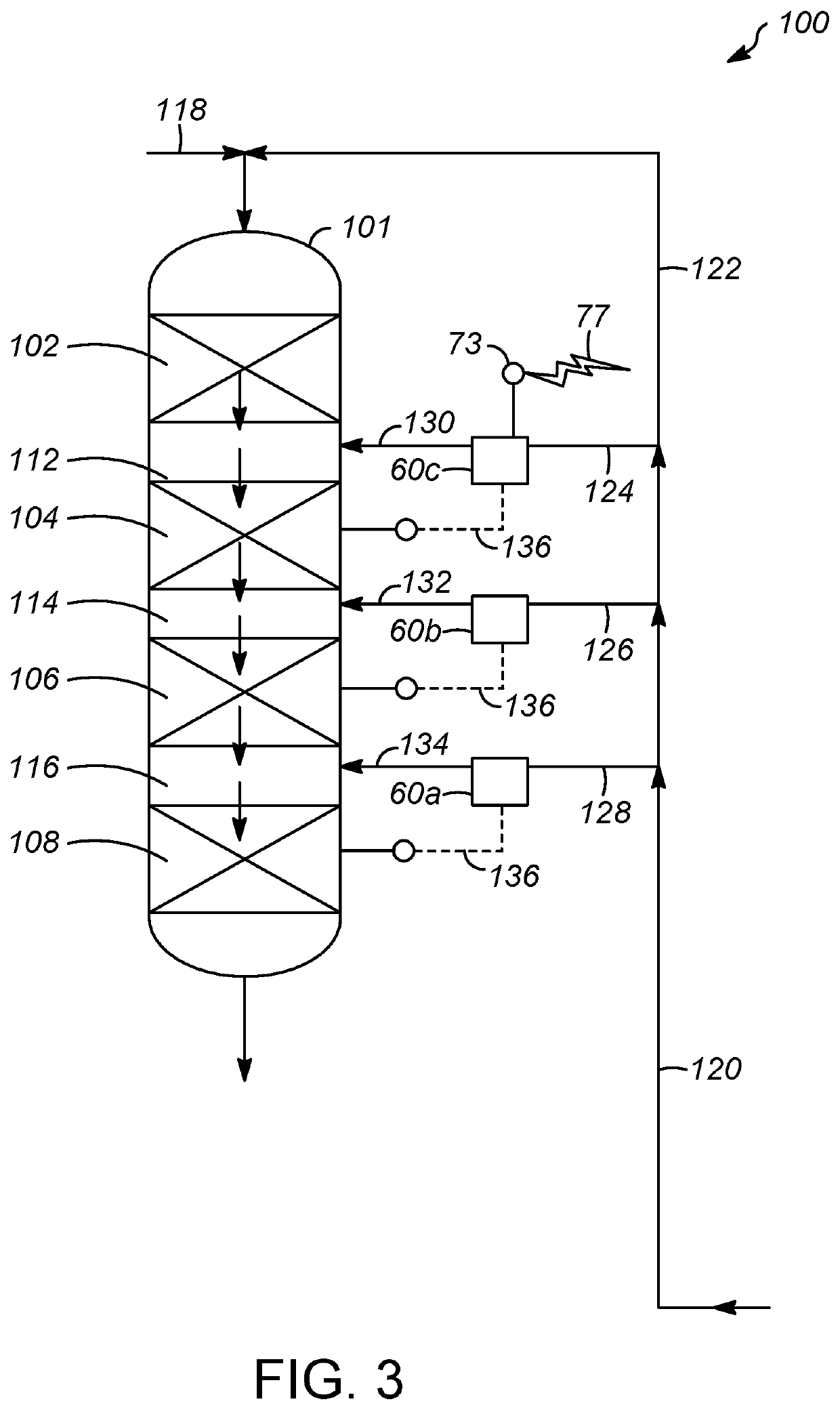
[0077]In simulated examples of the present invention, it was determined that by using a turbine 60 instead of a control valve, the quench temperature for a hydroprocessing reactor could be reduced by 5-10° C. It is believed that this could reduce the hydrogen demand requirements for the quench stream by up to 5% or alternatively debottleneck the hydrocarbon feed rate by a similar amount. Another option would be to use this reduction in the quench hydrogen demand to shift hydrogen to the reactor inlet. Additionally, or alternatively, the reduction in the quench hydrogen demand reduces the power consumption of the recycle gas compressor used in association the hydrogen containing gas stream. For an FCC unit, it was determined that by using a turbine 60 instead of a control valve, the catalyst to oil (feedstock) ratio could be increased with an increase in yield (as opposed to increase in undesired byproducts) which increases the profitability of the FCC unit or allow for more feed whi...

specific embodiments

[0085]While the following is described in conjunction with specific embodiments, it will be understood that this description is intended to illustrate and not limit the scope of the preceding description and the appended claims.

[0086]A first embodiment of the invention is a recovered electric power measuring system comprising (a) at least one processor; (b) at least one memory storing computer-executable instructions; and (c) at least one receiver configured to receive data from a sensor on an electrical powerline connected to an electrical generator which is connected to a turbine, the turbine in fluid communication with a vapor stream wherein the turbine reduces the pressure of the vapor stream and the resulting lower pressure vapor stream reduces a partial pressure of a hydrocarbon vapor or is injected into a reactor to reduce a temperature in the reactor. An embodiment of the invention is one, any or all of prior embodiments in this paragraph up through the first embodiment in t...


PUM

PropertyMeasurementUnit
residence timeaaaaaaaaaa
densityaaaaaaaaaa

Abstract

A process for reducing pressure of a vapor stream wherein the vapor stream rotates a turbine wheel within the turbine to transmit rotational movement to an electrical generator and generate electricity. The resulting lower pressure vapor stream reduces a partial pressure of a hydrocarbon vapor or is injected into a reactor to reduce a temperature in the reactor. A recovered electric power measuring system comprises at least one processor; at least one memory storing computer-executable instructions; and at least one receiver configured to receive data from a sensor on an electrical powerline connected to a generator of a turbine, the turbine in fluid communication with a vapor stream wherein the turbine reduces the pressure of the vapor stream and the resulting lower pressure vapor stream is injected into a reactor to reduce a temperature in the reactor or to reduce a partial pressure of hydrocarbon vapor in the reactor.

Description

RELATED APPLICATIONS[0001]This application claims priority to U.S. Provisional Patent Application No. 62 / 644,104 filed on Mar. 16, 2018, the entirety of which is incorporated herein by reference.FIELD OF THE INVENTION[0002]This invention relates generally to vapor streams that are used in a chemical processing or refining plant as a dilution fluid or a quench fluid, and more particularly to processes wherein such vapor streams pass through a turbine to lower a pressure of the vapor stream and recover energy from the pressure reduction. A recovered electric power measuring system comprises at least one processor; at least one memory storing computer-executable instructions; and at least one receiver configured to receive data from a sensor on an electrical powerline connected to a generator of a turbine, the turbine in fluid communication with a vapor stream wherein the turbine reduces the pressure of the vapor stream and the resulting lower pressure vapor stream is injected into a r...

Claims


Application Information

Patent Timeline
Patent Type & Authority Patents(United States)
IPC IPC(8): F02C3/28C01B3/38F02C6/18C01B3/00F02C3/20G05B15/02G06N5/02
CPCG05B15/02G06N5/02F01K23/064F01K17/04
Inventor FREY, STANLEY J.COUCH, KEITH A.EIZENGA, DONALD A.HARRIS, JAMES W.EBNER, THOMAS A.
Owner UOP LLC
Why Eureka
Try Eureka