Heat treatment apparatus for high-quality graphene synthesis

a heat treatment apparatus and graphene technology, applied in the field of heat treatment apparatus for high-quality graphene synthesis, can solve the problems of difficult formation of graphene formed by cvd, damage to the graphene deposited on the catalytic metal film, etc., to achieve easy separation of heater parts, enhance deposition efficiency, and facilitate maintenance

Active Publication Date: 2022-01-04
CHARMTRON
View PDF19 Cites 0 Cited by
  • Summary
  • Abstract
  • Description
  • Claims
  • Application Information

AI Technical Summary

Benefits of technology

[0017]The present invention has an advantage of enhancing deposition efficiency by depositing a plurality of graphenes on a catalytic metal film in a deposition chamber by forming a supply roller and a winding roller in a upper roll chamber and forming a lower direction shift roller in a lower roll chamber.
[0018]Further, the present invention has an advantage of facilitating maintenance by easily separating a heater part in the deposition chamber from a deposition chamber body.
[0019]Further, the present invention has an advantage of facilitating maintenance by forming a door in the deposition chamber.
[0020]Further, the present invention has an advantage of easily blocking and reflecting heat by disposing a heater between the catalytic metal films and installing a shield around the catalytic metal film, thereby enhancing heat efficiency required for deposition.
[0021]Further, the present invention has an economic effect of reducing costs required for deposition by depositing both surfaces of the catalytic metal film by a heater.
[0022]Further, the present invention has an advantage of adjusting tension of the catalytic metal film by positioning both a supply roller and a winding roller in an upper roll chamber.

Problems solved by technology

When such a device is used, it is difficult to form the graphene formed by CVD and it is possible to sufficiently predict a problem that process defects occur due to the penetration of foreign materials.
Further, a deposition chamber is horizontally placed and there is a possibility to generate damage to the graphene deposited on the catalytic metal film in the deposition chamber.

Method used


Image

  • Heat treatment apparatus for high-quality graphene synthesis
  • Heat treatment apparatus for high-quality graphene synthesis
  • Heat treatment apparatus for high-quality graphene synthesis

Examples


Embodiment Construction

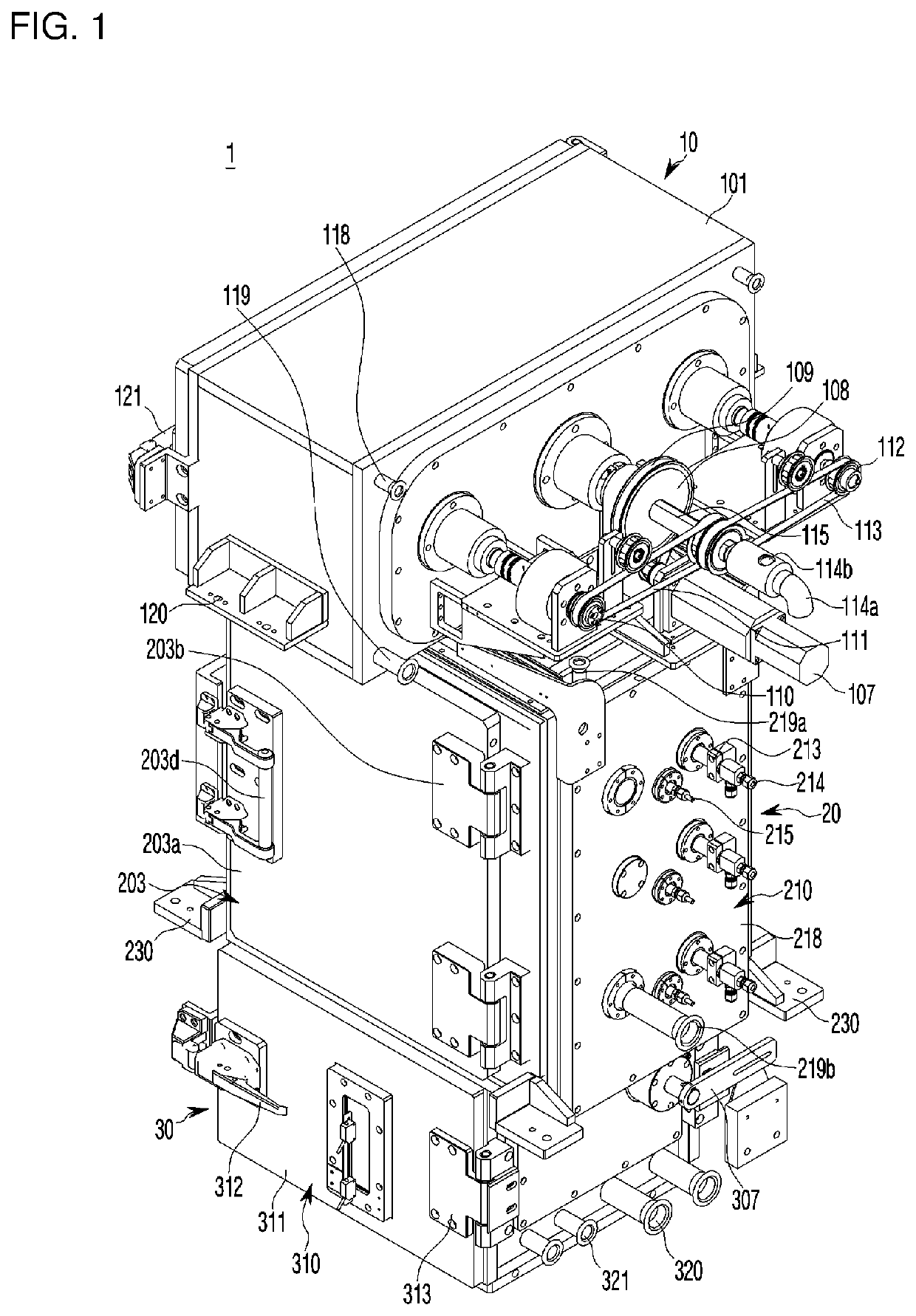
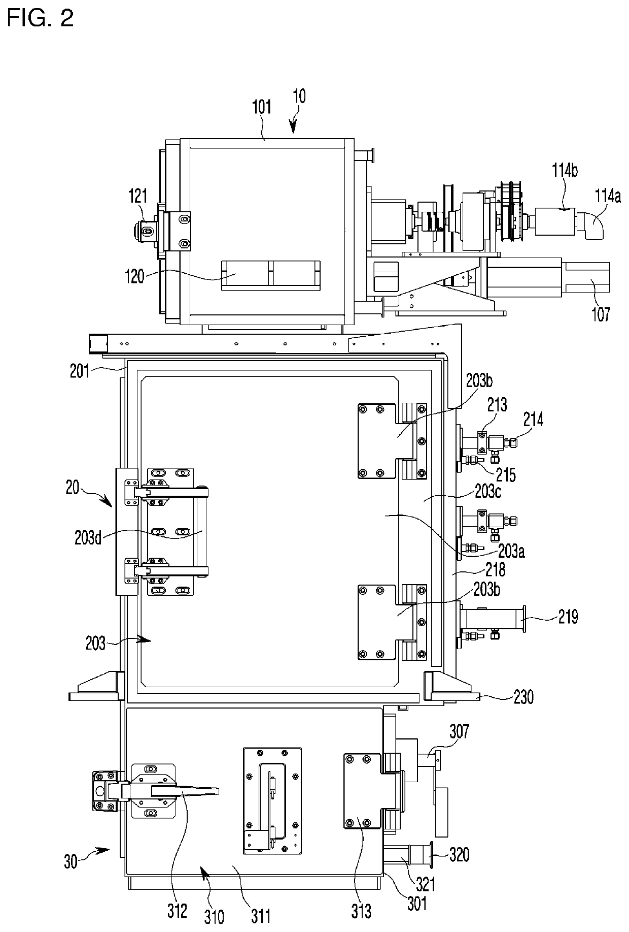
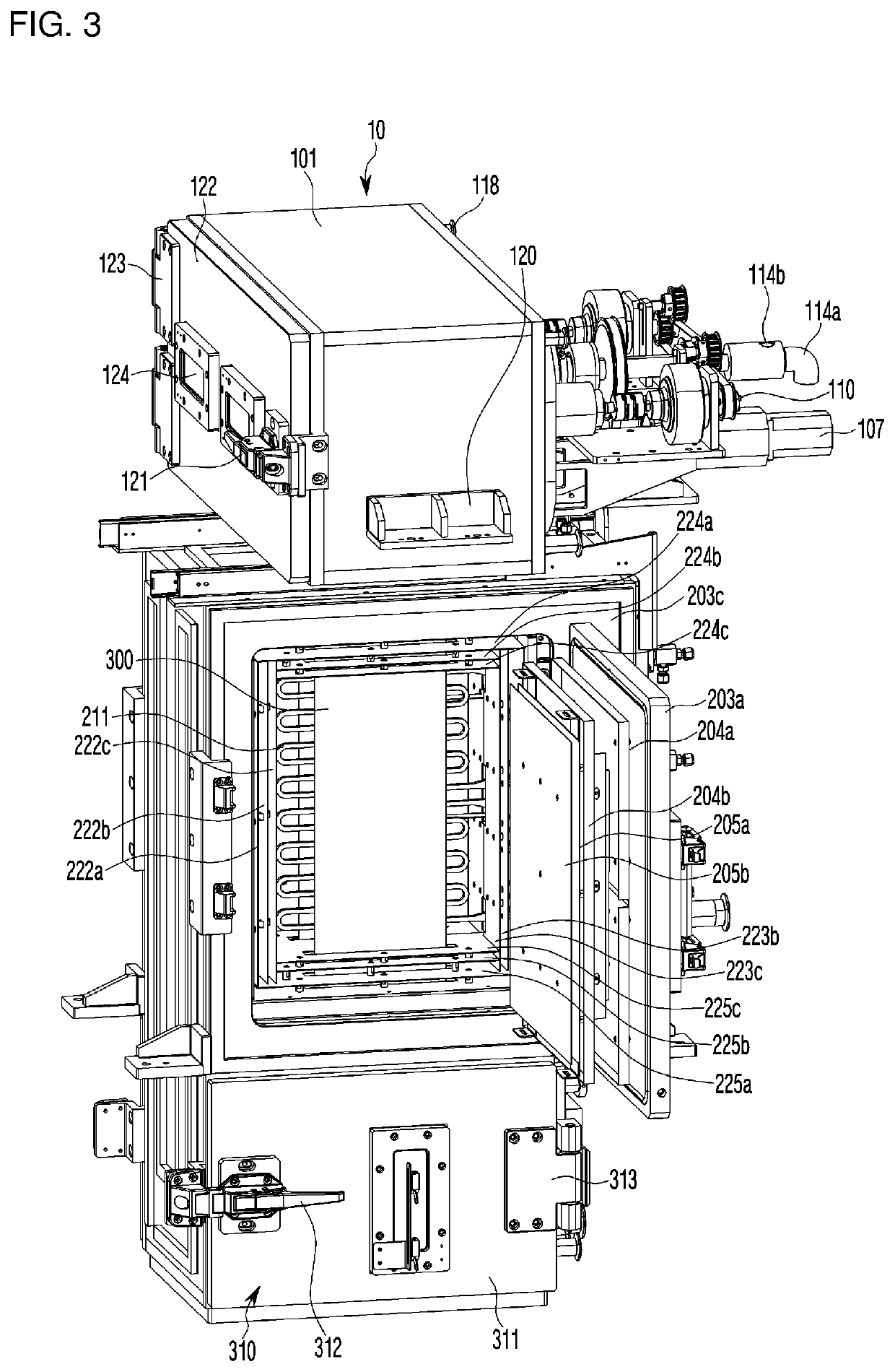
[0030]A best embodiment of the present invention provides a heat treatment apparatus for high-quality graphene synthesis comprising: an upper roll chamber, a deposition chamber 20 connected to the upper roll chamber to deposit graphene on a catalytic metal film, and a lower roll chamber mounted on a lower portion of the deposition chamber, in which the upper roll chamber includes a supply roller supplying the catalytic metal film and a winding roller winding the catalytic metal film deposited with the graphene, the lower roll chamber includes a lower direction shifting roller shifting a direction of the catalytic metal film which is supplied from the supply roller, deposited with the graphene in the deposition chamber, and wound on the winding roller, and in the deposition chamber, a catalytic metal film at a supply side transferred from the supply roller to the lower direction shifting roller and a catalytic metal film at a discharge side transferred from the lower direction shifti...


PUM

PropertyMeasurementUnit
temperatureaaaaaaaaaa
friction forceaaaaaaaaaa
frictionaaaaaaaaaa

Abstract

A heat treatment apparatus for high-quality graphene synthesis comprises an upper roll chamber, a deposition chamber connected to the upper roll chamber to deposit graphene on a catalytic metal film, and a lower roll chamber mounted on a lower portion of the deposition chamber. The upper roll chamber includes a supply roller and the lower roll chamber includes a lower direction shifting roller shifting a direction of the catalytic metal film supplied from the supply roller. In the deposition chamber, a catalytic metal film at a supply side transferred from the supply roller to the lower direction shifting roller and a catalytic metal film at a discharge side transferred from the lower direction shifting roller to a winding roller are passed, and a heater portion is mounted around the catalytic metal film at the supply side and the catalytic metal film at the discharge side.

Description

TECHNICAL FIELD[0001]The present invention relates to a heat treatment apparatus for high-quality graphene synthesis, and more particularly, to a heat treatment apparatus for high-quality graphene synthesis capable of more effectively depositing graphene on a catalytic metal film.BACKGROUND ART[0002]Generally, graphene is a material having a two-dimensional planar structure having a honeycomb shape in which carbons are connected with each other in the form of a hexagonal shape, and has a very large feature that its thickness is very thin and transparent, and electric conductivity is very high. Attempts have been made to apply the graphene to a transparent display or a flexible display using these features.[0003]A conventional method for manufacturing a graphene film is described in Korean Patent Publication No. 10-2012-0111659 (Method for manufacturing film including graphene, published on Oct. 10, 2012).[0004]In the above publication patent, for mass production, there are disclosed...

Claims


Application Information

Patent Timeline
Patent Type & Authority Patents(United States)
IPC IPC(8): C23C16/46B65H23/26C23C16/26B01J35/06B65H37/00B65H18/08C23C16/54C01B32/186B01J35/02B65H18/14B65H18/16
CPCC23C16/463B01J35/02B01J35/06B65H18/08B65H18/145B65H18/16B65H23/26B65H37/00C01B32/186C23C16/26C23C16/46C23C16/54C23C16/545B65H2301/4146B01J2523/00B65H2301/5114B65H2701/172C01B32/184B01J35/065B65H2301/34
Inventor KIM, YONG KI
Owner CHARMTRON
Why Eureka
Try Eureka