Support element for implantation into or between subject's bones, and implant component and implant system containing the same

a support element and bone technology, applied in the field of elastically expandable support elements for implantation into or between subjects' bones, can solve the problems of affecting the function of the patient, and affecting the ability of the patient to fully recover, so as to achieve the effect of restoring the single collapsed bon

Active Publication Date: 2022-02-01
HSIEH JUI YANG
View PDF1 Cites 0 Cited by
  • Summary
  • Abstract
  • Description
  • Claims
  • Application Information

AI Technical Summary

Benefits of technology

[0008]As for implantation between a subject's bones, the conventional devices for intervertebral fusion are the intervertebral cages, which can be roughly divided into those of a unitary structure and those of a composite structure. Common unitary-structure cages are in the shape of a disc-shaped, straight bullet-shaped, or banana-shaped for example, with a simple structural design that depends on a complicated tool for implantation and for preventing nerve and blood vessel injuries. Clinically, therefore, a unitary-structure intervertebral cage often falls short of its required dimensions such that the areas of contact between the cage and the adjacent vertebrae are not large enough to avoid pressure concentration (which may cause a subsidence or a extrusion of the intervertebral cage from the vertebrae) or promote intervertebral fusion (the failure of which may lead to the formation of a pseudoarthrosis). Composite-structure intervertebral cages either incorporate a screw or have an expandable structure. The screw-type cages, though featuring enhanced fixation, add to the difficulty of surgical operation and are applicable only in anterior intervertebral fusion. The expandable-structure intervertebral cages can be further divided into the medial-lateral expansion type and the caudal-cranial expansion type, both of which enable relatively large areas of contact and increased fixation but have rather intricate mechanical structures, including, for example, a large number of articulations and points of stress concentration. These complex structures not only limit the amount of bone graft packaged that can be put into each cage, but also increase the chances of long-term fatigue failure and pseudoarthrosis formation between vertebrae.
[0020]Therefore, the support element, the implant component, and the implant system of the present invention have the following beneficial effects:
[0021]1. The present invention provides a support element that stays in a contracted configuration, and hence remains relatively small, before implantation into a subject's bone or between two connected bones so as to facilitate the implantation, allowing a minimally invasive, small-incision surgical operation to be performed clinically.
[0023]3. If necessary, a plurality of the support elements of the present invention can be nested inside one another in the distended configuration after implantation into a bone or between two connected bones, and the nesting process can continue until the support provided by the entire implant system reaches the desired level. Thus, in the limited, tiny space in a single collapsed bone or between two connected bones, a plurality of the support elements of the invention can be put together to effectively restore the single collapsed bone or provide support between the connected bones. The number of the support elements to be implanted depends on the height of the bone to be restored or the distance between the connected bones to be supported. Theoretically, a single bone or the space between two connected bones can be filled with as many support elements of the invention as needed.
[0025]5. The support element of the present invention has a hollow nestable structure, which can be filled with an autologous, heterologous, or artificial bone graft as clinically needed to help increase the density of, grow, and thereby heal a fractured bone.

Problems solved by technology

In cases where screws may easily get loose because of a patient's osteoporotic conditions, there is no other choice than to enlarge the incision and use more screws to fixate more vertebrae, but more complications may also ensue from such a time-consuming, blood-losing spinal fixation operation.
Some common complications an elderly patient may develop are stiffness in the back, cardiopulmonary failure, and infection.
As to minimally invasive percutaneous vertebroplasty or kyphoplasty, the “bone cement” used in the operation may leak.
A serious leak of bone cement into blood vessels may result in arterial thrombosis, venous thrombosis, or stroke.
If a lot of bone cement leaks to the spinal cord or nerve roots and subsequently cures (generating high heat during the curing process), the surrounding nerves may be severely compressed or damaged.
Moreover, when bone cement exists permanently as a filler in a vertebra, the low bone-compatibility and extremely high hardness of bone cement may give rise to bone resorption, hinder the healing of a fracture in the vertebra, or even fracture a neighboring vertebra.
Clinically, therefore, a unitary-structure intervertebral cage often falls short of its required dimensions such that the areas of contact between the cage and the adjacent vertebrae are not large enough to avoid pressure concentration (which may cause a subsidence or a extrusion of the intervertebral cage from the vertebrae) or promote intervertebral fusion (the failure of which may lead to the formation of a pseudoarthrosis).
The screw-type cages, though featuring enhanced fixation, add to the difficulty of surgical operation and are applicable only in anterior intervertebral fusion.
These complex structures not only limit the amount of bone graft packaged that can be put into each cage, but also increase the chances of long-term fatigue failure and pseudoarthrosis formation between vertebrae.
As is well known in the art, implants in or between a subject's bones must not be complicated mechanical assemblies, or they tend to fatigue, disintegrate, or fail after persistent use in the human body.
In addition, such implants are preferably highly biocompatible or even conducive to the healing of bone fractures and therefore must not include materials that are rarely used, or not allowed to be used, in the human body.

Method used


Image

  • Support element for implantation into or between subject's bones, and implant component and implant system containing the same
  • Support element for implantation into or between subject's bones, and implant component and implant system containing the same
  • Support element for implantation into or between subject's bones, and implant component and implant system containing the same

Examples


Embodiment Construction

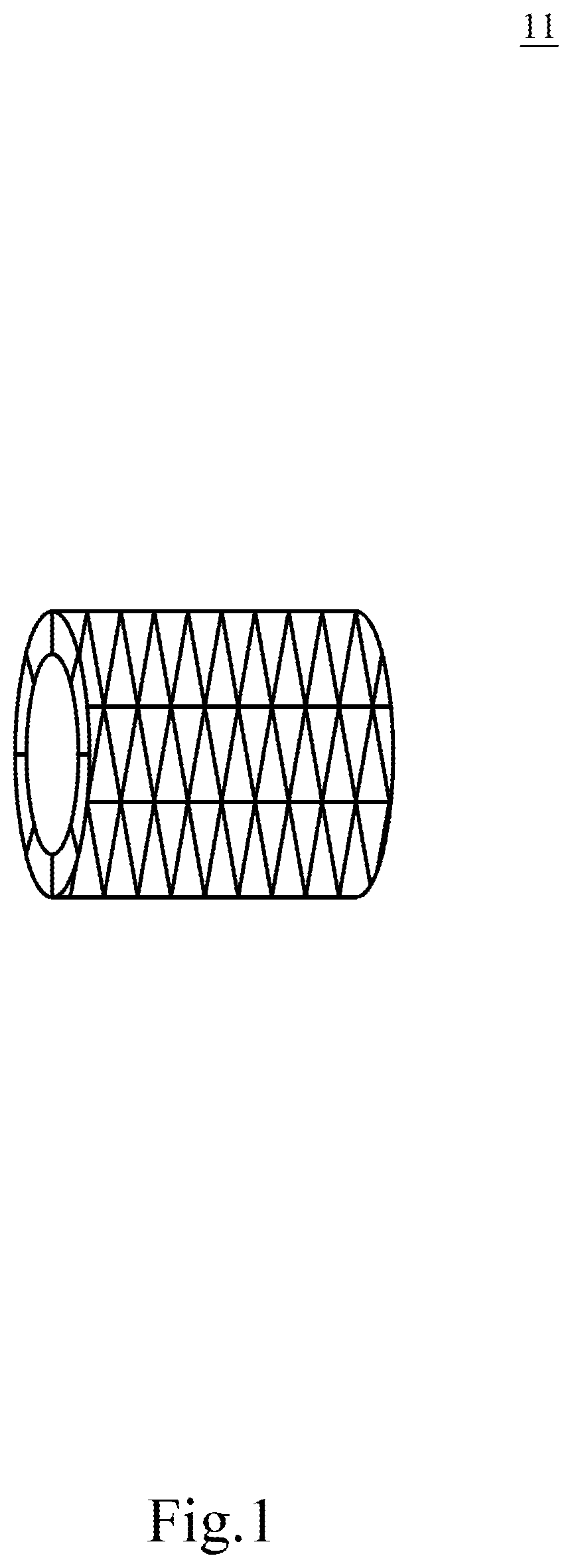
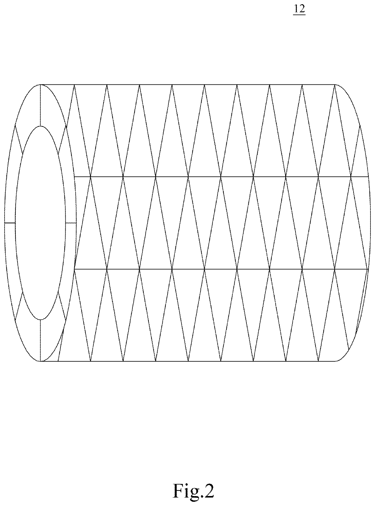
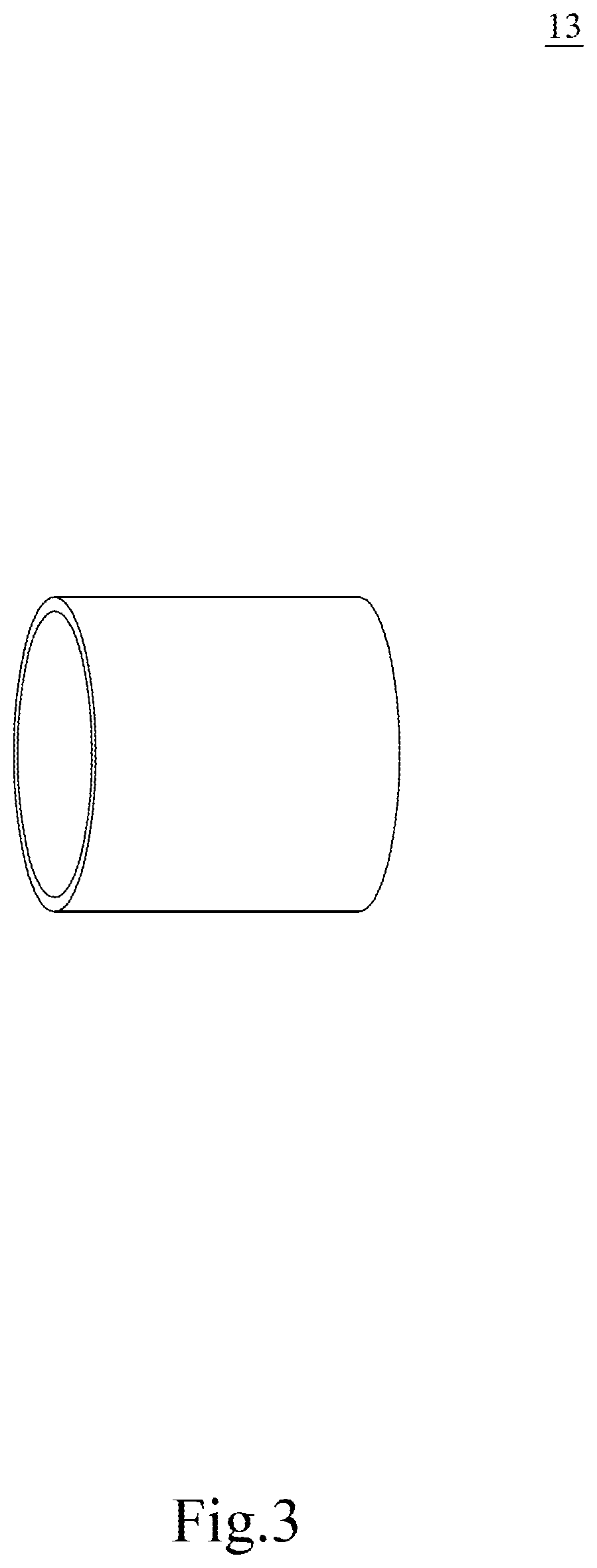
[0043]The details and technical solution of the present invention are hereunder described with reference to accompanying drawings. For illustrative sake, the accompanying drawings are not drawn to scale. The accompanying drawings and the scale thereof are not restrictive of the present invention.

[0044]The use of “or” means “and / or” unless stated otherwise. The use of “comprise” means not excluding the presence or addition of one or more other components, steps, operations, or elements to the described components, steps, operations, or elements, respectively. Similarly, “comprise,”“comprises,”“comprising”“include,”“includes,” and “including” are interchangeable and not intended to be limiting. As used herein and in the appended claims, the singular forms “a,”“an,” and “the” include plural referents unless the context dictates otherwise. The terms “a”, “an,”“the,”“one or more,” and “at least one,” for example, can be used interchangeably herein.

[0045]The present invention is more deta...


PUM


Abstract

The present invention provides a support element for implantation into or between a subject's bones, characterized in that: the support element is a hollow nestable structure having expandable elasticity, and can be in a contracted configuration or a distended configuration. The present invention also provides an implant component, comprising: the support element; and a limiting member to prevent the support element from expanding and thereby keep the support element in the contracted configuration. The present invention also provides an implant system applicable to a subject's spine, the implant system comprising: the support element as a first support element; and optionally one or a plurality of the support elements in the hollow nestable structure of the first support element. The support element can be nested until the support provided by the entire implant system reaches the desired level.

Description

BACKGROUND OF THE INVENTION1. Technical Field[0001]The present invention relates to a device to be implanted into a subject's bone or between two connected bones. More particularly, the invention relates to an elastically expandable support element for implantation into or between a subject's bones, and an implant component and implant system containing the same.2. Description of Related Art[0002]The societies many of us live in are aging or aged, which raises concerns about health issues of the elderly. A senior citizen tends to suffer from osteoporosis, degenerative bone diseases, and so on due to the deterioration of body functions, or is prone to such diseases as compression fracture and degenerative disc disease that result from prolonged improper posture caused typically by insufficient muscle strength. The following paragraphs briefly state some indications for treatment in or between a subject's bones and how such treatments are performed.[0003]Treatment within a subject's b...

Claims


Application Information

Patent Timeline
Patent Type & Authority Patents(United States)
IPC IPC(8): A61F2/44A61F2/46A61F2/30
CPCA61F2/4465A61F2/4611A61F2002/30092A61F2002/30235A61F2002/30545A61F2002/30593A61F2002/30604A61B17/8852A61B17/8858A61F2/446A61F2/4455A61B17/7094A61L27/06A61F2002/30579A61F2002/30565A61F2002/30914A61L2430/38
Inventor HSIEH, JUI-YANG
Owner HSIEH JUI YANG
Why Eureka
Try Eureka