Unit for controlling a controlled valve for abstracting an airflow from a pressurized airflow of an aircraft

a technology of controlled valves and airflow, applied in the field of turbines, can solve problems such as inability to adapt the gains of correctors, risk of contact, and large variability

Active Publication Date: 2022-02-15
SN DETUDE & DE CONSTR DE MOTEURS DAVIATION S N E C M A
View PDF22 Cites 2 Cited by
  • Summary
  • Abstract
  • Description
  • Claims
  • Application Information

AI Technical Summary

Benefits of technology

[0020]The invention aims at overcoming the drawbacks mentioned above in particular the variability of the control law connecting the control current to be delivered to the position of the flaps of the controlled valve, the variability of the control law generating dead control ranges, by providing a control unit for regulating the temperature of the bled stream making it possible to compensate for the dead range of the control current of the control law of the controlled valve.
[0026]a switch coupled at the outlet of the comparator and configured to deliver to the valve control system a maximum control current or a minimum control current based on the positive or negative sign of the error signal, the maximum control current making it possible to switch the shutter of said valve in a first position defining a fully closed state of the valve and the minimum control current making it possible to switch the shutter of said valve in a second position defining a fully open state of the valve, and
[0028]The valve control system can be an electro-pneumatic system like those described in the document FR 2 774 357. The control system can thus be a torque motor of the valve which actuates the cylinder making it possible to modify the position of the flaps in the case where the shutter is formed by at least two flaps. The control system and the valve can be integrated in the same block.
[0029]The regulator of the regulation system is thus configured to operate in all-or-nothing mode. The use of an all-or-nothing type regulator with a phase lead provides ideal performances for an air bleed system of an aircraft, as well as extremely simple adjustment.
[0031]The (1+τp)-type phase lead, with τ a time constant of a system and p the signal, applied on the signal supplying the comparator of the control unit, i.e. on the signal resulting from the difference between the setpoint temperature and the measured temperature, allows overcoming this problem.
[0037]The time constant of the valve is applied modulo an adjustment constant called adjustment gain. The adjustment gain allows adjusting the phase lead based on the correction desired by the control unit. A gain of 1 provides a maximum phase lead, which regularly switches the current control. A gain less than 1 allows limiting the switching frequency of the control and thus lengthening the service life of the valve.

Problems solved by technology

During an increase in speed, for example during the transition from a ground idle speed to a take-off speed in a turbomachine for an aeronautical engine, the centrifugal force exerted on the turbine rotor tends to bring the blade tips of the turbine ring before the turbine ring have had time to expand under the effect of the increase in temperature related to the increase in speed which generates a risk of contact.
The regulation carried out using this FAV valve however poses problems which arise from the valve itself, in particular in the case where such a FAV system does not have a flap position feedback that allows knowing the position of the flaps.
On the other hand, the dispersion related to the manufacture and the one linked to the environmental conditions generate significant variability in the law connecting the control current sent to the torque motor and the position of the flaps.
The problem of monitoring the control current to be sent therefore comes directly from this feature.
The gains of the corrector cannot be adapted to the position of the valve, because this position is unknown, which leads to very slowly crossing the dead area of the scoop-valve.
This implies a very slow response time of the regulation.

Method used


Image

  • Unit for controlling a controlled valve for abstracting an airflow from a pressurized airflow of an aircraft
  • Unit for controlling a controlled valve for abstracting an airflow from a pressurized airflow of an aircraft

Examples


Embodiment Construction

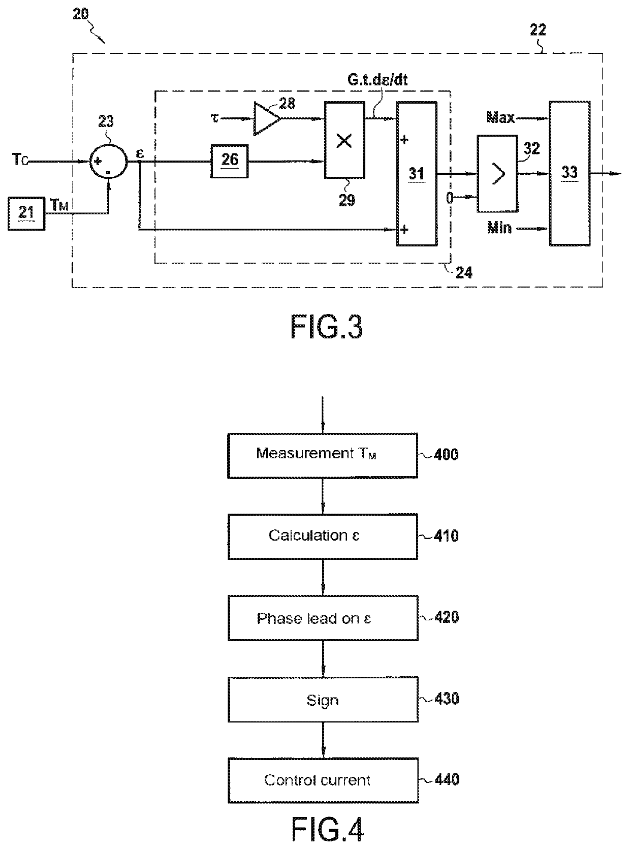
[0064]FIG. 2 schematically represents a turbomachine 1 of an aircraft provided with a heat exchange assembly according to one embodiment of the invention.

[0065]The turbojet engine 1 is of the turbofan and double-body type and has a longitudinal axis X. The turbojet engine comprises in particular a fan 2 which delivers an air stream divided into a primary stream FP flowing in a primary flowpath 3 of the primary stream FP and into a secondary stream FS flowing in a secondary flowpath 4 of the secondary stream FS coaxial with the primary flowpath 3. The primary flowpath 3 extends between a core shroud 30 and an inter-flowpath compartment 34, and the secondary flowpath 4 extends between the inter-flowpath compartment 34 and an outer shroud 40. From upstream to downstream in the direction of flow of the primary stream FP, the primary flowpath 3 comprises a low-pressure compressor 5, a high-pressure compressor 6, a combustion chamber 7, a high-pressure turbine 8 and a low-pressure turbine...


PUM


Abstract

A system for regulating a thermal parameter associated with a heat exchange assembly of a turbomachine includes at least one device for measuring or estimating the thermal parameter, a controlled valve acting on the flow rate of a fluid in the assembly, and a regulator including a comparator determining the sign of an error signal relating to the difference between the thermal parameter and a setpoint. The regulator further includes a switch configured to deliver, based on the sign, to a valve control system, a maximum control current switching the valve in a closed state or a minimum control current switching the valve in an open state, and a phase-shifter configured to apply on the error signal a phase advance determined from an estimate of a time constant of the control system.

Description

BACKGROUND OF THE INVENTION[0001]The invention relates to the general field of turbomachines for aeronautical gas turbine engines. It concerns more particularly the regulation of the supply temperature of an air bleed system for an aircraft.[0002]An aircraft, such as an airplane, comprises a fuselage in which a cockpit and a passenger cabin are arranged, and at least one turbomachine. Such a turbomachine comprises an engine and a fan at which air bleeds can be performed. Such bleeds are carried out by a system called bleed system, comprising a plurality of valves and a heat exchanger. These valves allow air bleed from various air streams circulating in the engine, in particular a high-pressure high-temperature air stream, bled from a pressurized air stream from at least one compressor stage of the engine, and a cold fan air stream, bled downstream of the fan, for example in a secondary flowpath where a cold air stream circulates. The high-pressure air stream and the fan air stream c...

Claims


Application Information

Patent Timeline
Patent Type & Authority Patents(United States)
IPC IPC(8): F02C6/08F02C9/18B64D13/06F02C7/18F28D21/00
CPCF02C6/08F02C9/18B64D2013/0618F02C7/185F05D2220/323F05D2260/213F05D2270/101F05D2270/303F28D2021/0021Y02T50/60
Inventor DJELASSI, CEDRIK
Owner SN DETUDE & DE CONSTR DE MOTEURS DAVIATION S N E C M A
Why Eureka
Try Eureka