
Methods and systems for a multi-wavelength illumination system

a multi-wavelength illumination and system technology, applied in the field of multi-wavelength light sources, can solve the problems of difficulty in coupling efficiency into the fiber or light guide, lack of sufficient led power in some desired wavelength regions, etc., and achieve the effect of improving efficiency, reducing excessive losses in the system, and improving optical output efficiency

Active Publication Date: 2022-05-03
PHOSEON TECHNOLOGY INC
View PDF9 Cites 0 Cited by
  • Summary
  • Abstract
  • Description
  • Claims
  • Application Information

AI Technical Summary

Benefits of technology

The illumination system described in this patent is designed to make the most use of LED light by improving the efficiency of the optical output. This is achieved by using a dichroic mirror and arranging the LEDs and lens assembly in a way that reduces excessive losses in the system. The use of a stack of two aspheric lenses at close distance to the LED surface also improves light collection efficiency. Additionally, multiple LEDs can be tiled together to create a larger emission surface and increase the power output of the illumination. The system is cost-effective and easy to assemble.

Problems solved by technology

However, the coupling efficiency into the fiber or light guide may be challenging in some cases due to the large emitting area and Lambertian-type of emission distribution.
In addition, lack of sufficient LED power in some desired wavelength regions has been a problem.

Method used


Image

  • Methods and systems for a multi-wavelength illumination system
  • Methods and systems for a multi-wavelength illumination system
  • Methods and systems for a multi-wavelength illumination system

Examples


Embodiment Construction

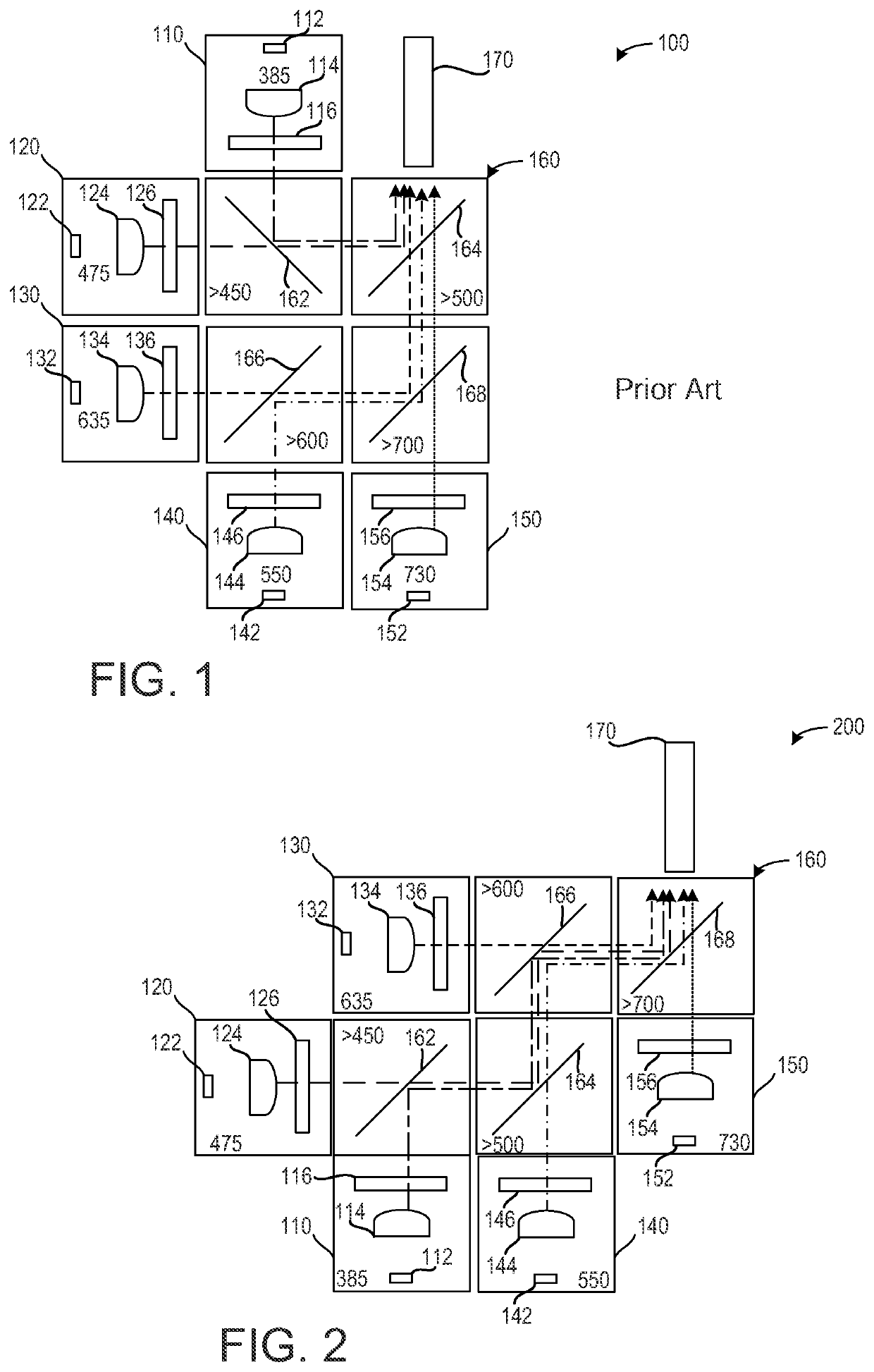
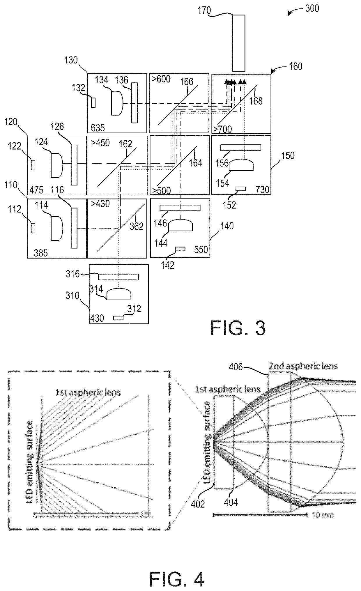
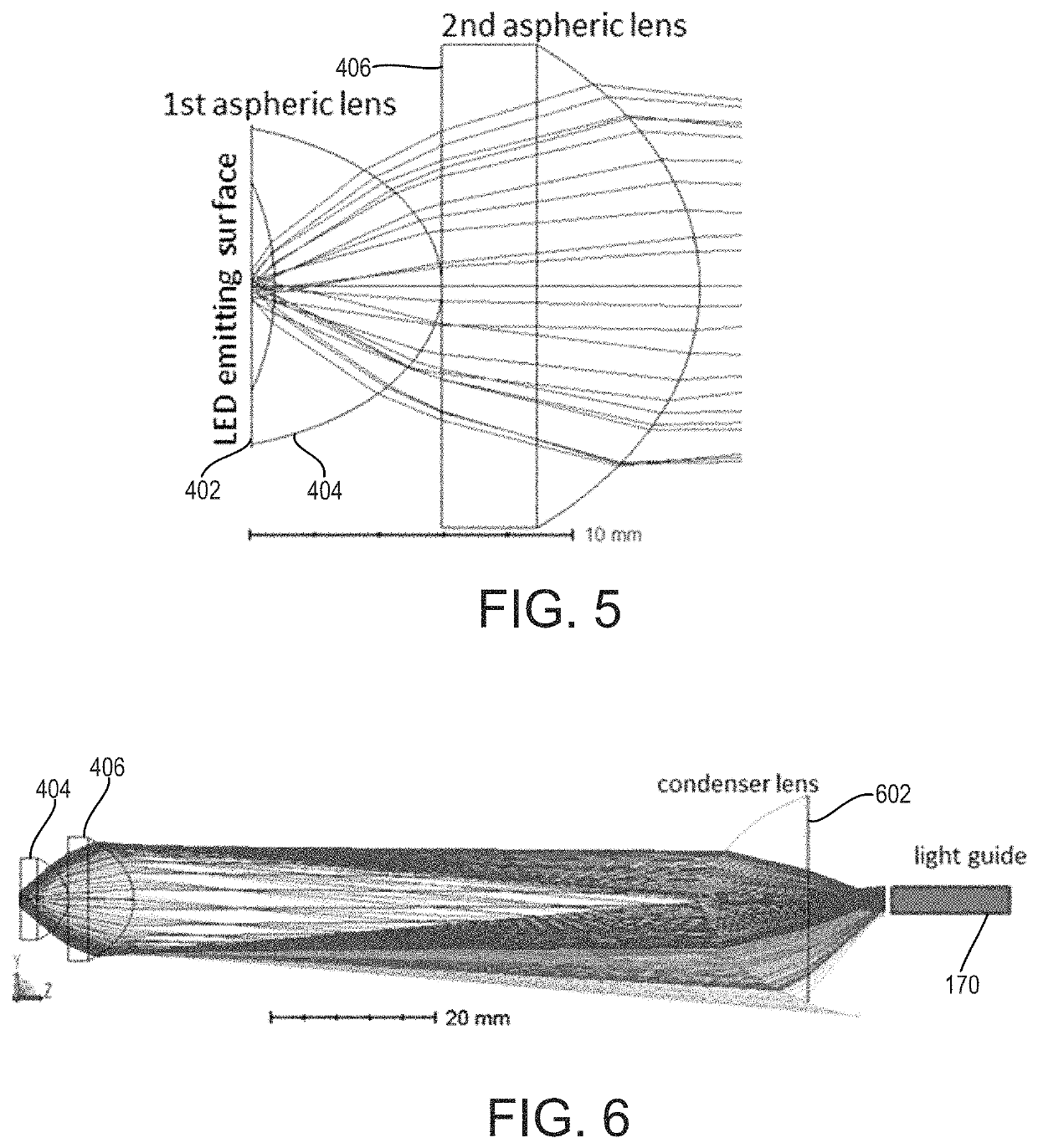
[0015]The following description relates to systems and methods for multi-wavelength light sources configured to provide high irradiance illumination at multiple narrow band wavelength regions (less than 20 nm). The light-sources may be configured to be light sources for microscopy and / or endoscopy. The desired spectral bands may extend from ultra-violet (UV) to near infrared (NIR) wavelength. FIG. 1 shows a first embodiment of a previous example of a multi-color illumination system. FIG. 2 shows a second embodiment of a multi-color illumination system. FIG. 3 shows a third embodiment of the multi-color illumination system. FIG. 4 shows a first embodiment of a lens assembly. FIG. 5 shows a second embodiment of the lens assembly. FIG. 6 shows an embodiment of a condenser lens.

[0016]Some examples of the approach described herein utilize a configuration of a dichroic mirror which has a larger transmission loss (˜10%) than reflection loss (˜2%). By arranging the LEDs (light emitting diod...


PUM

PropertyMeasurementUnit
threshold distanceaaaaaaaaaa
wavelengthaaaaaaaaaa

Abstract

Methods and systems are provided for a light emitting device. In one example, an illumination system comprises a plurality of light sources, each light source of the plurality of light sources comprising a light emitting diode configured to emit a collimated beam of light of a color, a plurality of reflective optical components oriented identically to one another, wherein the plurality of reflective optical components is configured to direct the first collimated beam, the second collimated beam, the third collimated beam, the fourth collimated beam, and the fifth collimated beam along a common axis, and an output positioned to receive light along the common axis, wherein the output is configured to generate an output beam.

Description

CROSS REFERENCE TO RELATED APPLICATIONS[0001]The present application claims priority to U.S. Provisional Application No. 62 / 916,688, entitled “MULTI-WAVELENGTH ILLUMINATION SYSTEM,” and filed on Oct. 17, 2019, the entire contents of which are hereby incorporated by reference in their entirety for all purposes.FIELD[0002]Embodiments of the subject matter disclosed herein relate to multi-wavelength light sources that may provide high irradiation illumination at multiple narrow-band wavelength regions for microscopy and / or endoscopy. The desired spectral bands may extend from ultra-violet (UV) to near infrared (NIR) wavelength.BACKGROUND[0003]In some examples, the light is coupled in an optical fiber and / or light guide for the flexibility and versatility to work with other instruments. Light emitting diodes (LED) may be used as the light source for its simplicity, lower cost, and robustness. However, the coupling efficiency into the fiber or light guide may be challenging in some cases...

Claims


Application Information

Patent Timeline
Patent Type & Authority Patents(United States)
IPC IPC(8): F21V5/00F21V9/20G02B21/06G02B23/24F21V5/04G02B27/14F21Y113/10F21Y115/10
CPCF21V5/008F21V5/04F21V9/20G02B21/06G02B23/2469G02B27/141F21Y2113/10F21Y2115/10F21S2/005F21Y2113/13F21V7/0033G02B19/0014G02B19/0061
Inventor JA, SHIOU-JYH
Owner PHOSEON TECHNOLOGY INC
Learn More