Binder jetting and supersolidus sintering of ferrous powder metal components

a technology of ferrous powder and metal components, applied in the field of additive manufacturing of metal parts, can solve the problems of high cost of spherical ga powder grades, inability and require the additional expense of post-printing infiltration alloys to achieve high densities

Active Publication Date: 2022-10-11
STACKPOLE INT POWDER METAL LLC
View PDF25 Cites 0 Cited by
  • Summary
  • Abstract
  • Description
  • Claims
  • Application Information

AI Technical Summary

Benefits of technology

[0006]Highly wear resistant components in industrial and mining sector applications, such as slurry pump rotors and drill sections, are conventionally cast or machined from forgings. These alloys necessarily have very high hardness, for example 50-65 HRc, and are difficult to machine. It is not easy to design complex features for manufacturability reasons. Accordingly, one or more non-limiting embodiments utilize BJAM and sintering to facilitate the manufacture of complex shapes, with good wear resistant microstructures and high hardness levels. According to various of these embodiments, the design freedom and material properties offer advantages over conventional processing.
[0038]One or more embodiments facilitates the manufacture of complexly shaped ferrous alloy components to high densities, hardnesses, and toughnesses without the need for secondary operations to achieve the net desired component shape and size.
[0039]According to various embodiments, the BJAM printing process facilitates new low volume markets for complex, tough, hard components.

Problems solved by technology

Spherical GA powder grades are expensive and have found initial application in high value markets such as Aerospace and Medical Devices.
Water Atomized (WA) grades of iron have been used for BJAM processes, but may require the additional expense of post-printing infiltration alloys to achieve high densities.
In addition, final properties are limited to the given the microstructure and densities produced.
These alloys necessarily have very high hardness, for example 50-65 HRc, and are difficult to machine.
It is not easy to design complex features for manufacturability reasons.
Additive Manufacturing typically requires expensive specialized iron powders (e.g., gas atomized iron powders).

Method used


Image

  • Binder jetting and supersolidus sintering of ferrous powder metal components
  • Binder jetting and supersolidus sintering of ferrous powder metal components

Examples


Embodiment Construction

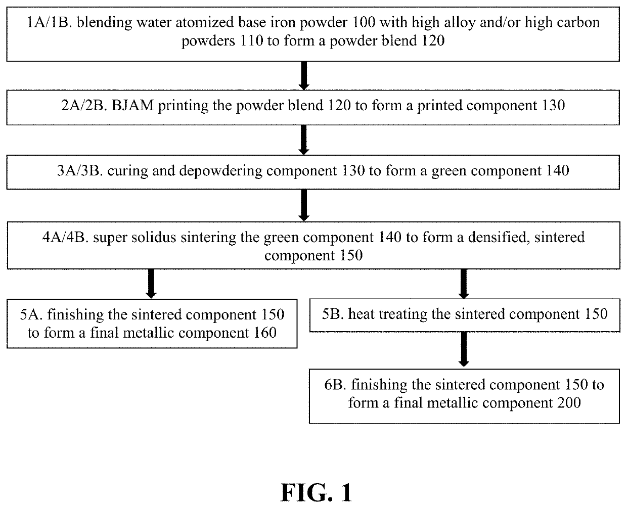
[0047]FIG. 1 is a flowchart illustrating various methods of manufacturing metallic components according to alternative embodiments. Steps 1A-5A provide manufacturing steps for a non-heat treated component 160, while steps 1B-6B provide manufacturing steps for a heat-treated component 200.

[0048]At step 1A / 1B, base iron powder and / or a prealloyed base iron powder 100 is blended with a master alloy powder 110 to form a powder blend 120.

[0049]According to various embodiments, the base iron powder 100 comprises at least 10, 20, 30, 40, 50, 60, 70, 80, 90, 95, and / or 100% water atomized (WA) elemental iron powder. According to various embodiments, the iron powder 100 comprises a standard, low-cost, WA iron powder. According to various embodiments, the WA iron powder 100 has a D40, D45, D50, D55, D60, D65, D70, D75, and / or D80 particle size of (a) less than 150, 140, 130, 125, 120, 115, 110, 105, 100, 95, 90, 85, 80, 70, 65, 60, 55, 50, 45, 40, 35, and / or 30 um, (b) more than 20, 25, 30, 3...


PUM

PropertyMeasurementUnit
D50 particle sizeaaaaaaaaaa
porosityaaaaaaaaaa

Abstract

A densified, high-strength metallic component is manufactured by: binder jet additive manufacture (BJAM) printing a powder blend to form a printed part; and super solidus sintering the printed part to form the metallic component, which may then be heat treated. The powder blend comprises a blend of water atomized base iron powder and a high-carbon master ferroalloy powder. The high-carbon ferroalloy powder introduces high concentrations of carbon into a powder blend that is readily BJAM printable.

Description

CROSS REFERENCE TO RELATED APPLICATIONS[0001]The subject application claims priority to U.S. Provisional Patent Application No. 62 / 669,450, filed May 10, 2018, the subject matter of which is incorporated herein by reference in its entirety.BACKGROUNDField of the Invention[0002]Various embodiments relate generally to additive manufacturing of metal parts, and more particularly to binder jet additive manufacturing of metal parts.Description of Related Art[0003]Processes for Additive Manufacturing of metallic parts have been developed for the fabrication of complex geometries in a variety of materials. Technologies such as Selective Laser Melting (SLM) and Electron Beam Melting (EBM) of particulate metals, typically produced by Gas Atomisation (GA), are known. Spherical GA powder grades are expensive and have found initial application in high value markets such as Aerospace and Medical Devices.[0004]The Binder Jetting Additive Manufacturing (BJAM) process is also known for prototyping ...

Claims


Application Information

Patent Timeline
Patent Type & Authority Patents(United States)
IPC IPC(8): B22F10/10B22F3/11B22F9/08B22F3/10B33Y80/00B33Y10/00B33Y70/00B22F1/052
CPCB22F10/10B22F3/1035B22F3/1103B22F3/1146B22F9/082B22F2009/0828B22F2301/35B22F2302/10B22F2304/10B22F2998/10B33Y10/00B33Y70/00B33Y80/00C22C33/0278Y02P10/25C22C1/055B22F10/14B22F1/052B22F10/34B22F1/09B22F3/1021B22F2003/248B22F3/10B22F3/24
Inventor SHIVANATH, ROHITHSHEN, PENGWILLIAMS, VINCENT
Owner STACKPOLE INT POWDER METAL LLC
Why Eureka
Try Eureka