Stabilized LiDAR system and method for stabilization

a lidar system and stabilization technology, applied in lasers, instruments, laser details, etc., can solve the problems of noise contribution, difficult or impossible separation of reflected signal and noise with increasing distance, and greatly limited types of suitable lasers

Active Publication Date: 2022-10-25
ROBERT BOSCH GMBH
View PDF18 Cites 0 Cited by
  • Summary
  • Abstract
  • Description
  • Claims
  • Application Information

AI Technical Summary

Benefits of technology

[0012]The means for evaluation may additionally be configured to make a determination of the setpoint wavelength to the transmission maximum of a receiving filter associated with the LiDAR system. In particular, the means for evaluation may therefore include a means for spectral measurement of the receiving filter. The means for spectral measurement of the receiving filter may be in particular a device, which measures the receiving filter spectrally with the aid of a defined reference radiation. The defined reference radiation may be in particular a LiDAR radiation obtainable by sequential wavelength-selective tuning of the laser in the dark phases of the LiDAR system, or it may be the light of a spectrally broadband light source. Implementation of the measuring / regulating method may be further improved in this way by offsetting not only the variations of the laser and the temperature variations but also manufacturing-induced variations in the receiving filter.
[0014]In the present invention includes the diversion of the control chain, which is customary in the related art, by measuring the wavelength instead of the temperature. The laser process variation in accordance with the present invention may therefore be compensated by adjusting the working temperature of the laser. In addition, temperature drifts occurring during operation may be offset with high precision since the effect of the temperature (i.e., the wavelength) is present directly as a control variable in a control chain according to the present invention, not just the deviation from the target temperature. A regulation solely on the basis of the temperature as the control variable is more error prone since the association between target temperature and setpoint wavelength, which is used for the regulation, may vary over time, and the system performance would therefore deteriorate progressively. However, in a control chain according to the present invention, the control is directed directly to the target value, i.e., the setpoint wavelength. Therefore, this definitely improves the stabilization in both the short term and the long term in comparison with the related art.
[0034]The advantage of this method is that it is possible not only to capture the temperature variations and variations of the laser during the manufacturing process, but also to capture the variations during production of the receiving filters. On the whole, this permits significant reduction in costs and assembly effort during production.

Problems solved by technology

Since the receiver in the receiving unit (detector, for example) is influenced by additional disturbances at the same time, separation of the reflected signal from the noise becomes increasingly more difficult or impossible with an increase in distance.
One important disturbance for LiDAR systems may be background light, which strikes the scenery at the same time.
This is also imaged on the detector via the receiving optical system and results in a noise contribution.
Although it is certainly possible to use such lasers, the types of suitable lasers are greatly limited.
If all possible process variations and temperature drifts are to be taken into account in selecting an appropriate filter, only a very broad filter may be used, if necessary, allowing a great deal of background light to pass through accordingly and thereby limiting the range of the LiDAR system.
This problem may be improved, for example, by direct selection of the required lasers from the production process, but this is associated with much higher costs.
However, it is problematic here that the relationship between the measured temperature at one site of the laser unit and the actually relevant temperature at the laser emitter chip, (i.e., in particular the temperature of the active region of the laser), is unknown or is known only approximately.
This limits the effective precision of such a temperature regulation and thus also limits the minimally achievable filter width.
A regulation solely on the basis of the temperature as the control variable is more error prone since the association between target temperature and setpoint wavelength, which is used for the regulation, may vary over time, and the system performance would therefore deteriorate progressively.
However, in this exemplary embodiment, a measurement is less possible linearly than in a differential method according to the first preferred specific embodiment.

Method used


Image

  • Stabilized LiDAR system and method for stabilization
  • Stabilized LiDAR system and method for stabilization
  • Stabilized LiDAR system and method for stabilization

Examples


Embodiment Construction

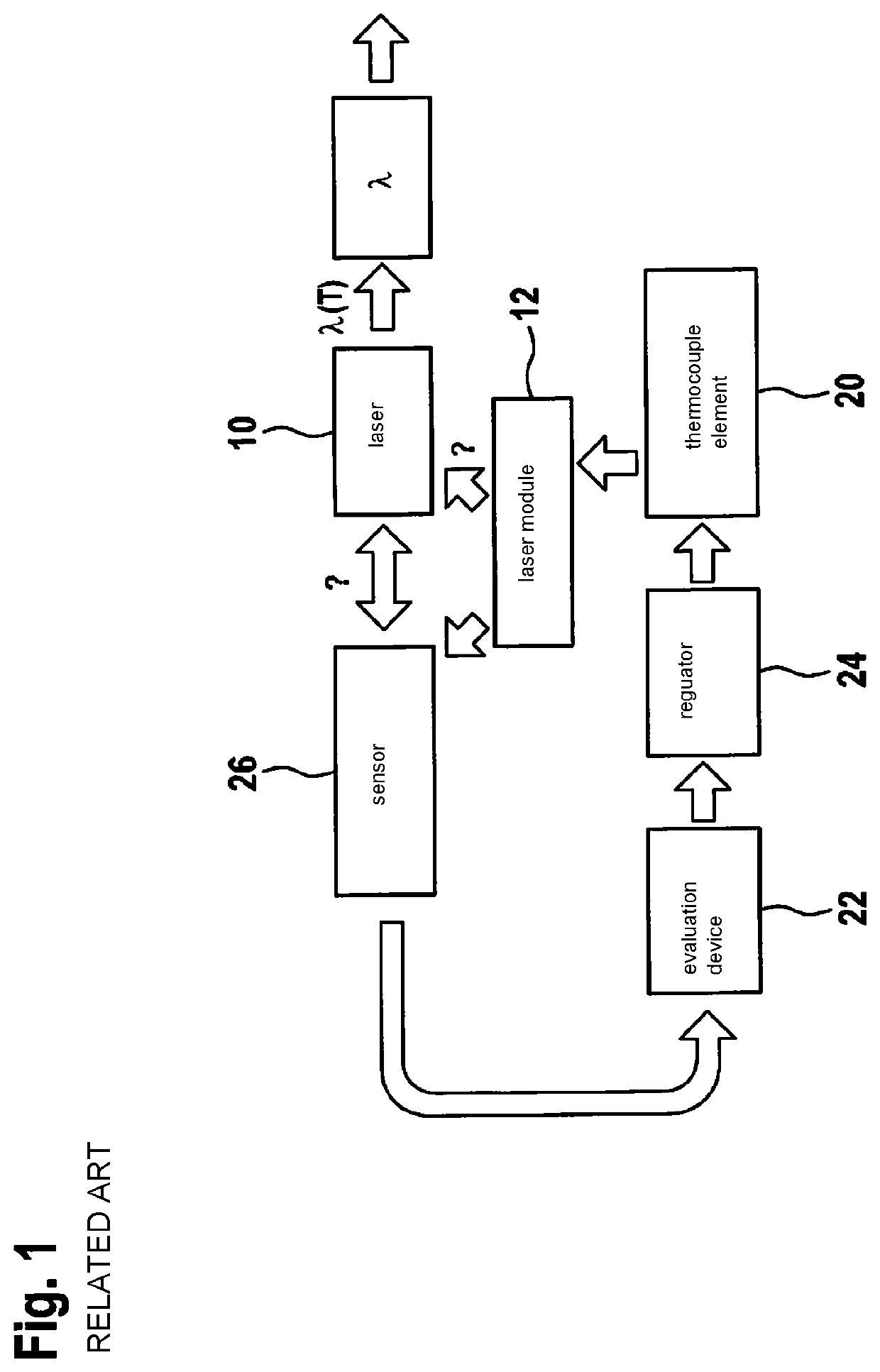
[0047]FIG. 1 shows a schematic diagram of a control chain for laser stabilization in the related art. The arrows drawn in the figure indicate the dependencies between the individual components of the control chain. The control chain shown in the figure includes a laser 10, laser 10 being designed for emission of monochromatic LiDAR radiation (wavelength λ) within a wavelength working range λ(T); a thermocouple element 20 being configured to set working temperature T of laser 10; a means for evaluation 22 being designed to determine a measure for the deviation from actual temperature Tactual to a setpoint temperature Tsetpoint from actual temperature Tactual of laser 10 measured by a sensor 26; and a means for regulation 24 being designed to control thermocouple element 20 on the basis of the measure of deviation determined by the means for evaluation 22 in such a way that working temperature T of laser 10 is set to a value corresponding to setpoint temperature Tsetpoint. Laser 10 ma...


PUM


Abstract

A stabilized LiDAR system and a method for stabilization. The LiDAR system includes a laser, the laser being designed for emission of monochromatic LiDAR radiation within a wavelength working range; a thermocouple element configured to set the working temperature of the laser; a means for evaluation, designed to determine, from the radiation emitted by the laser, a measure for the deviation from an actual wavelength of the radiation to a setpoint wavelength within the wavelength working range of the laser; and a means for regulation, designed to control the thermocouple element on the basis of the measure of deviation determined by the means for evaluation, in such a way that the working temperature of the laser is set to a value, at which the emitted monochromatic LiDAR radiation corresponds to the setpoint radiation.

Description

CROSS REFERENCE[0001]The present application claims the benefit under 35 U.S.C. § 119 of German Patent Application No. DE 102018209995.2 filed on Jun. 20, 2018, which is expressly incorporated herein by reference in its entirety.FIELD[0002]The present invention relates to a stabilized LiDAR system and a method for stabilization. The present invention relates in particular to a LiDAR system having improved temperature regulation for suppressing optical crosstalk and a method for wavelength stabilization in a corresponding LiDAR system.BACKGROUND INFORMATION[0003]Scanning LiDAR systems for detection of surroundings generally include a transmission unit and a receiving unit. The transmission unit generally generates a beam, which illuminates a certain portion of the scenery with the aid of a laser. The photons incident there are reflected or scattered and detected with the aid of the receiving optical system. Due to the scattering of the photons into a large space angle at the particul...

Claims


Application Information

Patent Timeline
Patent Type & Authority Patents(United States)
IPC IPC(8): G01S7/497H01S5/0687
CPCG01S7/497H01S5/0687G01S7/481
Inventor HATTASS, MIRKOKNECHT, TIMO
Owner ROBERT BOSCH GMBH
Why Eureka
Try Eureka