Window thermal profile calibration in additive manufacturing

a window thermal profile and additive manufacturing technology, applied in the field of additive manufacturing, can solve problems such as complicated problems

Active Publication Date: 2022-11-15
CARBON INC
View PDF68 Cites 2 Cited by
  • Summary
  • Abstract
  • Description
  • Claims
  • Application Information

AI Technical Summary

Benefits of technology

[0010]In some embodiments, said modifying step enhances at least one performance characteristic of said apparatus (e.g., by increasing a rate of production, by reducing a frequency of production failures thereon, by enhancing accuracy of object production thereon, by reducing defect formation in objects produced thereon, by resulting in more uniform polymerization, by increasing control over a green strength of the object, etc., including combinations thereof).

Problems solved by technology

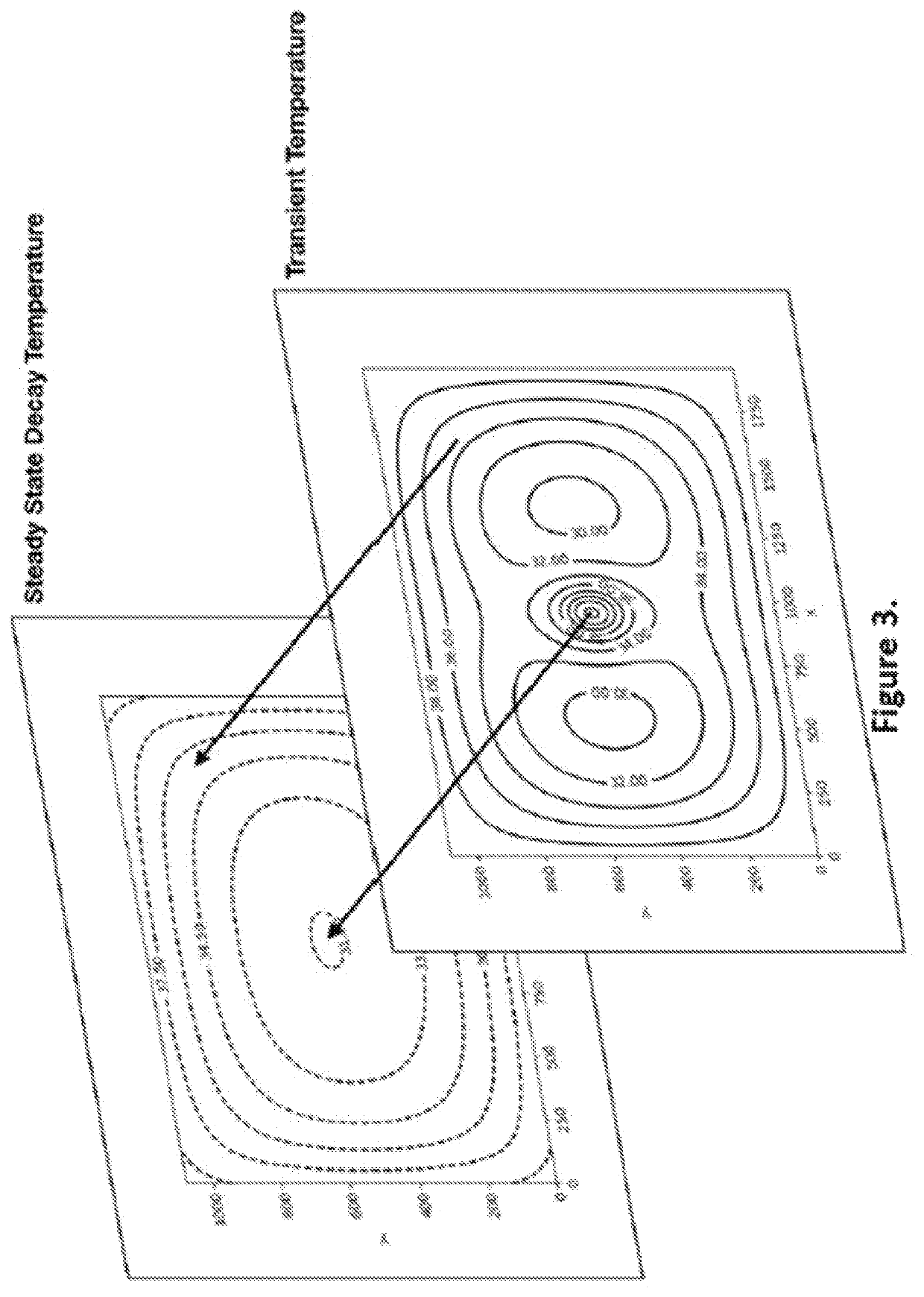
These issues are even further complicated as window designs for such apparatus has evolved, with different window designs having different thermal profiles.

Method used


Image

  • Window thermal profile calibration in additive manufacturing
  • Window thermal profile calibration in additive manufacturing
  • Window thermal profile calibration in additive manufacturing

Examples


Embodiment Construction

[0029]The present invention is now described more fully hereinafter with reference to the accompanying drawings, in which embodiments of the invention are shown. This invention may, however, be embodied in many different forms and should not be construed as limited to the embodiments set forth herein; rather these embodiments are provided so that this disclosure will be thorough and complete and will fully convey the scope of the invention to those skilled in the art.

[0030]As used herein, the term “and / or” includes any and all possible combinations or one or more of the associated listed items, as well as the lack of combinations when interpreted in the alternative (“or”).

[0031]“Unique identifier” and “unique identifier reader” as used herein refer to components of an automatic identification and data capture system. Suitable unique identifiers include, but are not limited to, bar codes (including one-dimensional and two-dimensional bar codes (QR codes)), near field communication (N...


PUM

PropertyMeasurementUnit
temperatureaaaaaaaaaa

Abstract

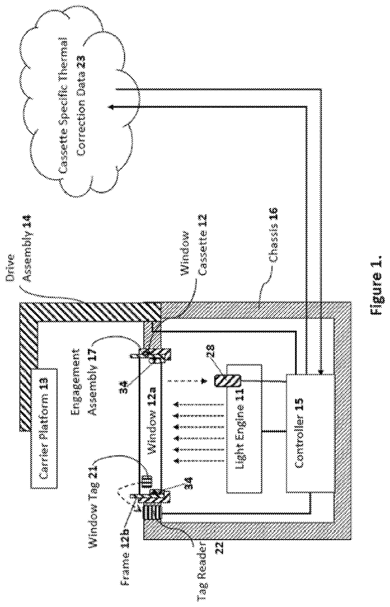
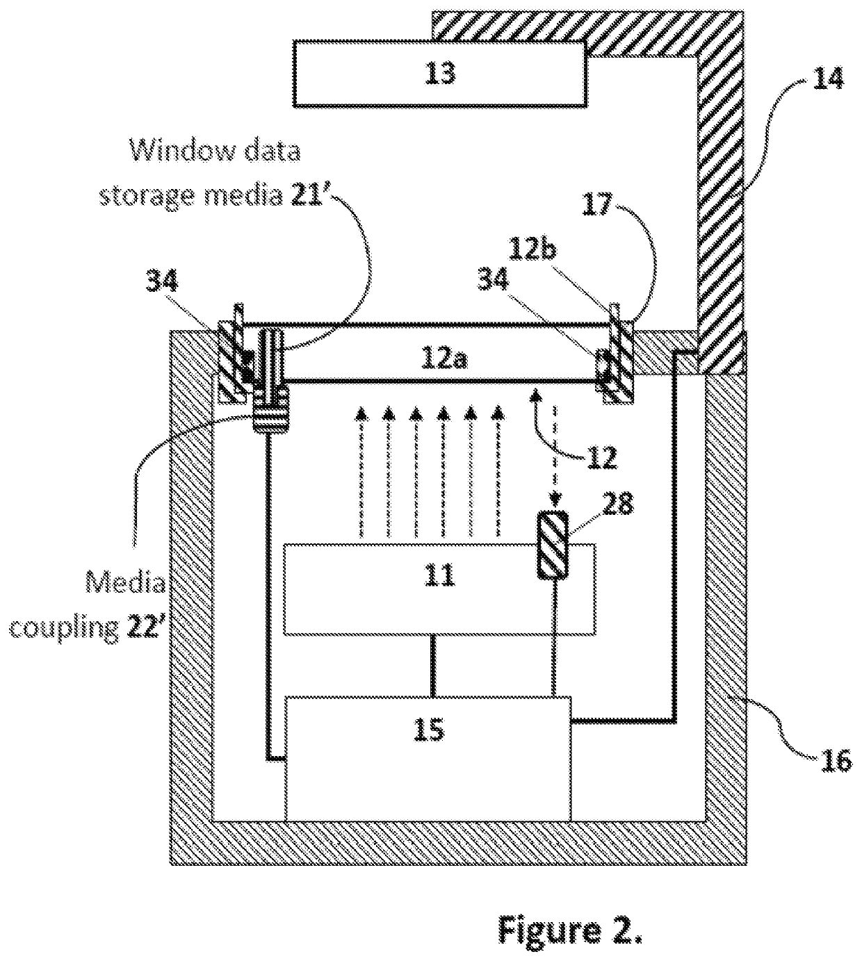
Methods, systems, and / or apparatuses for making an object on a bottom-up stereolithography apparatus that includes a light source (11), a drive assembly (14), optionally a heater (34) and / or cooler (34), and a controller (15). The light source, optional heater and / or cooler, and / or the drive assembly have at least one adjustable parameter that is adjustable by said controller. An example method comprises (a) installing a removable window cassette (12) on said apparatus in a configuration through which said light source projects, said window cassette comprising an optically transparent member (12a) having a build surface on which an object can be produced, and with said optically transparent member having at least one thermal profile associated therewith; and then (b) modifying said at least one adjustable parameter by said controller based on said at least one thermal profile of said optically transparent member; and then (c) producing the object on said build surface from a light-polymerizable liquid by bottom-up stereolithography.

Description

CROSS-REFERENCE TO RELATED APPLICATION[0001]This application is a 35 U.S.C. § 371 national phase application of International Application Serial No. PCT / US2019 / 062762, filed Nov. 22, 2019, which claims priority to U.S. Provisional Application Serial No. 62 / 774,384, filed Dec. 3, 2018, with the entire contents of each above-identified application hereby incorporated by reference.FIELD OF THE INVENTION[0002]The present invention concerns additive manufacturing, particularly stereolithography, including continuous liquid interface production (CLIP).BACKGROUND OF THE INVENTION[0003]A group of additive manufacturing techniques sometimes referred to as “stereolithography” create a three-dimensional object by the sequential polymerization of a light polymerizable resin. Such techniques may be “bottom-up” techniques, where light is projected into the resin onto the bottom of the growing object through a light transmissive window, or “top down” techniques, where light is projected onto the r...

Claims


Application Information

Patent Timeline
Patent Type & Authority Patents(United States)
IPC IPC(8): B29C64/245B33Y10/00B33Y30/00B33Y50/02B29C64/124B29C64/295B29C64/393
CPCB29C64/245B29C64/124B29C64/295B29C64/393B33Y10/00B33Y30/00B33Y50/02B29C64/259B33Y50/00
Inventor MOHSENIZADEH, DANIEL N.LAAKER, KYLETRUONG, RONALD A.
Owner CARBON INC
Why Eureka
Try Eureka