
Mobile communication system

Inactive Publication Date: 2001-06-21
MITSUBISHI ELECTRIC CORP
View PDF0 Cites 20 Cited by
  • Summary
  • Abstract
  • Description
  • Claims
  • Application Information

AI Technical Summary

Benefits of technology

[0013] Therefore, the phase synchronization can be precisely performed, and communication turbulence in a hand-over operation can be suppressed.
[0015] Therefore, even though the subscriber station moves to a zone of an adjacent ground radio base station during the communication, communication turbulence can be suppressed.
[0021] Therefore, the phase synchronization can be precisely performed, and communication turbulence in a hand-over operation can be suppressed.
[0034] Therefore, even though one link channel is disconnected by an accident or natural conditions, a lack of information can be prevented.

Problems solved by technology

However, the satellite functions only as a relay repeater, but the satellite has no function for adjusting the phase of a radio wave transmitted and received.
However, because the satellite has no function for adjusting a phase of radio wave, a phase shift between a radio wave directly transmitted from a ground radio base station and a radio wave transmitted from the ground radio base station through the satellite is generated in a subscriber station.
Therefore, even though a power of one of the radio waves is weakened, there is a problem that it is difficult to hand over the other radio wave to the subscriber station.

Method used


Image

  • Mobile communication system
  • Mobile communication system
  • Mobile communication system

Examples


first embodiment

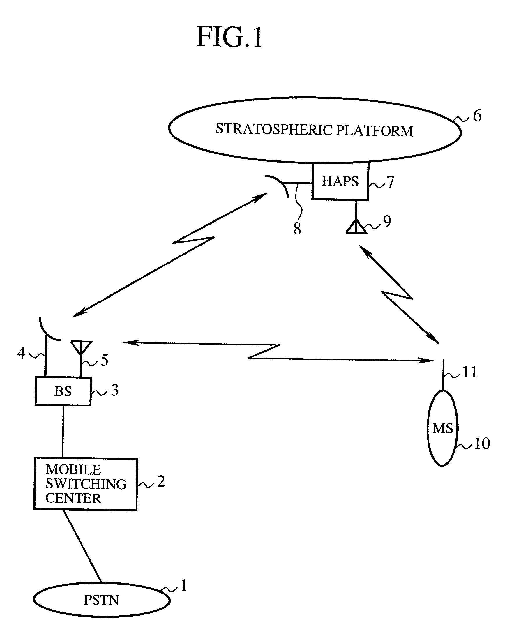
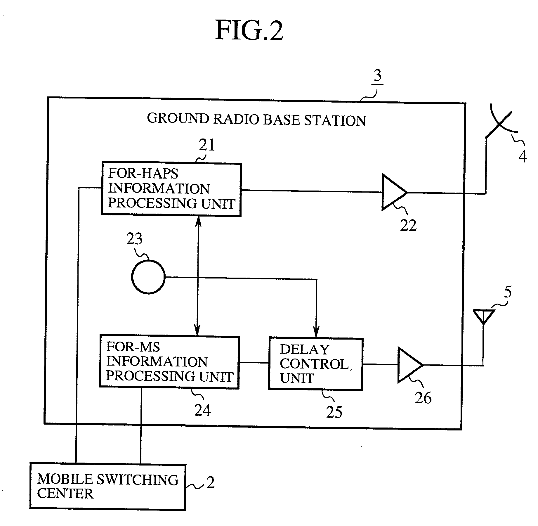
[0053] FIG. 1 is a constitutional diagram showing a mobile communication system according to the present invention. In FIG. 1, 1 indicates a public switching telephone network (PSTN). 2 indicates a mobile switching center, wire-connected with the PSTN 1, for controlling a ground radio base station 3. 3 indicates the ground radio base station (BS), arranged on the ground, for performing a two-way communication of information with a stratospheric platform base station 7 and performing a two-way communication of information with a subscriber station 10. 4 indicates a directional antenna for performing a radio communication with the stratospheric platform base station 7. 5 indicates an antenna for performing a radio communication with the subscriber station 10.

[0054] 6 indicates a stratospheric platform which is halted at an elevation of about 20 km from the ground (automatically halted at a prescribed position while using a power of propellers against a wind which is a low-density air ...

embodiment 2

[0089] FIG. 5 is a constitutional diagram showing a main portion of the subscriber station 10 of a mobile communication system according to a second embodiment of the present invention. In FIG. 5, 31 indicates an amplifier for amplifying the radio wave received in the antenna 11. 32 to 34 indicate a plurality of time slot detectors for respectively detecting time slots from the radio wave amplified in the amplifier 31. In the example shown in FIG. 5, a plurality of time slot detectors, of which the number is n, are prepared. 35 to 37 indicate a plurality of information detectors for respectively detecting information from the time slots detected in the corresponding time slot detector 32, 33 or 34, 38 indicates a delay time measuring unit for detecting a time difference (or a phase difference) between the time slots detected in the time slot detectors 32 to 34 and transmitting information of the phase difference to the delay control unit 25 of the ground radio base station 3.

[0090] ...

embodiment 3

[0100] In the second embodiment, the subscriber station 10 has one delay time measuring unit 38 (or one phase detecting unit), and the phase difference information is transmitted to the ground radio base station 3. However, in cases where a subscriber station can perform an information communication not only with one set of the ground radio base station 3 and the stratospheric platform base station 7 but also with a set of a plurality of ground radio base stations 3 and the stratospheric platform base station 7, it is applicable that a plurality of delay time measuring units 38 be arranged in the subscriber station 10 to transmit pieces of phase difference information to the plurality of ground radio base stations 3.

[0101] Therefore, even though the subscriber station 10 moves to a zone of an adjacent ground radio base station 3 during the communication, communication turbulence can be suppressed. That is, the subscriber station 10 can hand over phase difference information to anoth...


PUM


Abstract

In cases where a radio communication is performed between a ground radio base station and a subscriber station, when a delay time J passes after the transmission of a radio wave from the ground radio base station to a stratospheric platform base station, another radio wave relating to the same information as that indicated by the radio wave is transmitted from the ground radio base station to the subscriber station. Therefore, in the subscriber station, a phase of the radio wave directly transmitted from the ground radio base station is synchronized with a phase of the radio wave transmitted from the ground radio base station through the stratospheric platform base station. Accordingly, the subscriber station can change over from one radio wave, of which the strength is weakened, to another radio wave.

Description

CROSS-REFERENCE TO THE RELATED APPLICATION[0001] This application is a continuation of International Application No. PCT / JP99 / 03239, whose International filing date is Jun. 17, 1999, the disclosures of which Application are incorporated by reference herein.[0002] 1. Field of the Invention[0003] The present invention relates to a mobile communication system in which radio communication is performed between a ground radio base station and a subscriber station (for example, a fixed radio station, a semi-fixed radio station, a mobile station, a portable radio station and so on) by using a Time Division Multiple Access (TDMA) method, a Code Division Multiple Access / Time Division Duplex (CDMA / TDD) method or a Time Divided CDMA method.[0004] 2. Description of Related Art[0005] In a mobile communication system, communication of information is, for example, performed between a mobile station such as a mobile on-vehicle communication apparatus or a mobile portable communication apparatus and ...

Claims


Application Information

Patent Timeline
IPC IPC(8): H04B7/185
CPCH04B7/18504
Inventor UCHIDA, YOSHINORI
Owner MITSUBISHI ELECTRIC CORP
Learn More