
Magnetoresistive sensor

Inactive Publication Date: 2001-07-05
HITACHI GLOBAL STORAGE TECH JAPAN LTD
View PDF25 Cites 18 Cited by
  • Summary
  • Abstract
  • Description
  • Claims
  • Application Information

AI Technical Summary

Benefits of technology

[0014] Secondly, a high conductance oxidized stopper layer is disposed between the oxide protective layer and the soft magnetic free layer. The non-magnetic high conductance oxidized stopper layer prevents diffusion of oxygen from the oxide protective layer or propagation of stresses caused by oxides as far as the soft magnetic free layer and prevents degradation of the soft magnetic characteristic of the free layer. This can prevent lowering of the sensitivity of the spin valve film and, further, prevent lowering of the output. Further, disposition of the conductive layer causes elastic scattering of itinerane electrons at the boundary between the non-magnetic high conductance oxidized stopper layer and the oxide protective film to extend the mean free stroke length of itinerane electron to improve .DELTA.R more than the existent spin valve structure. As the material for the non-magnetic high conductance oxidized stopper layer, Cu, Pd, Pt, Os, Rh, Re, Ru, Ag and Au are generally used but the materials are not restricted to the foregoings so long as they are non-magnetic and conductive.
[0015] Thirdly, the thickness of the non-magnetic high conductance oxidized stopper layer is selected such that the interlayer coupling field is reduced to zero. Since the sensitivity of the spin valve film is lowered as the interlayer coupling field increases, the interlayer coupling field is desirably lower. When the non-magnetic high conductance oxidized stopper layer is disposed, the thickness of the non-magnetic high conductance oxidized stopper layer can be selected such that the interlayer coupling field is substantially reduced to zero since the interlayer coupling field changes along with the thickness of the conductive layer. This can prevent lowering of the sensitivity caused by increase in the interlayer coupling field.
[0016] According to this invention, a spin-valve type magnetic head more excellent in the sensitivity and capable of obtaining higher output than existent structure can be provided by introducing the oxide protective layer and the high conductance oxidized stopper layer to the spin-valve film. Further, magnetic reading / writing apparatus having favorable writing output and stability at high recording density can be obtained by using the magnetic head according to this invention.

Problems solved by technology

In the prior art for increasing the recording density in recording apparatus in recent years, it has been impossible to obtain magnetic recording apparatus having a sufficiently high recording density and, particularly, a magnetoresistive element in the reproducing portion thereof that operates at a sufficient sensitivity and output to the external magnetic field and, further, obtain favorable characteristic with sufficiently controlled stability for the output and it has been difficult to realize the function as the recording apparatus.

Method used


Image

  • Magnetoresistive sensor
  • Magnetoresistive sensor
  • Magnetoresistive sensor

Examples


example 2

[0053] Example 2

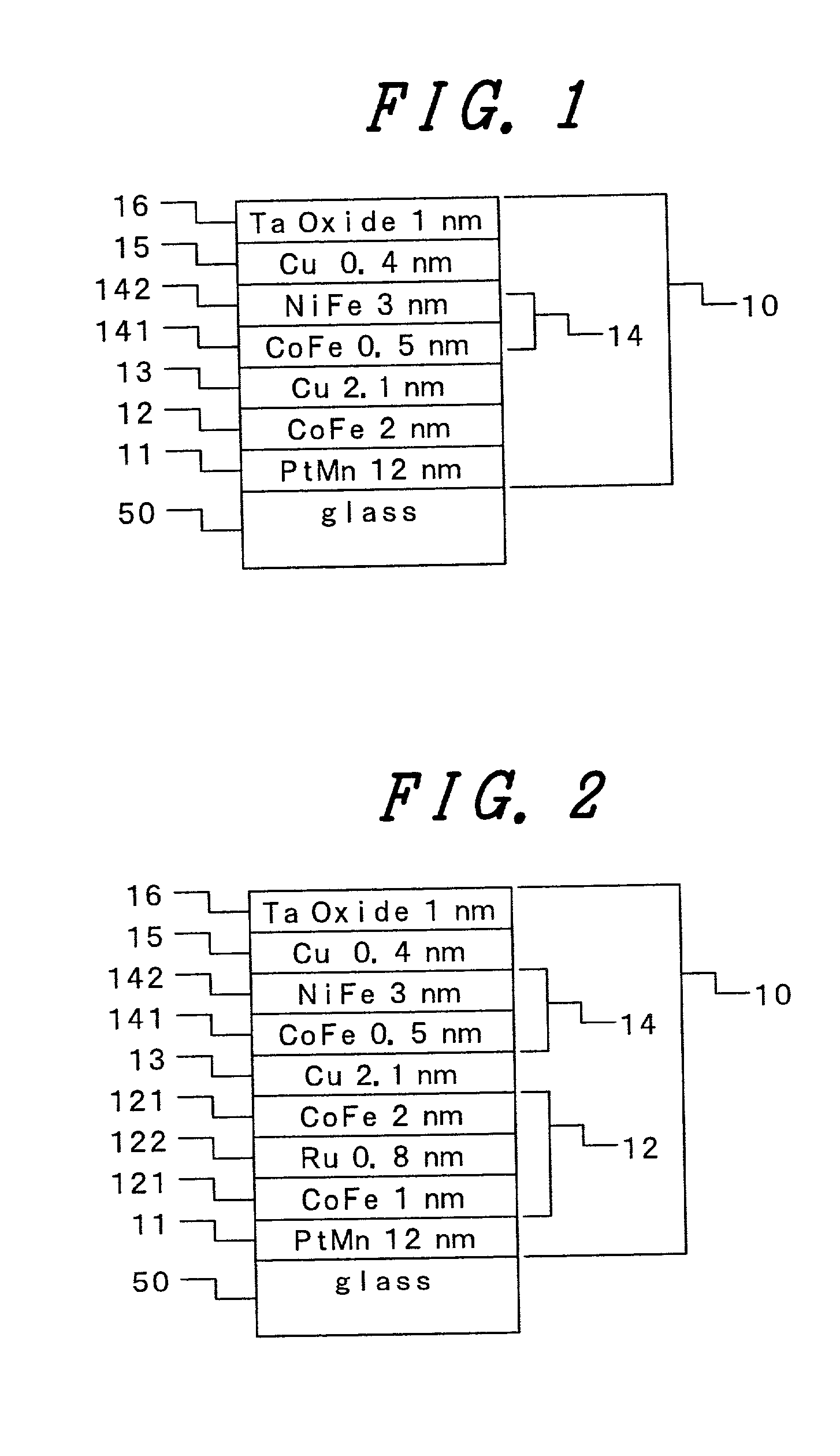
[0054] FIG. 2 illustrates an example of applying this invention to a spin valve type magnetoresistive film of another structure. The magnetoresistive lamination film 10 comprises an anti-ferromagnetic film 11, a ferromagnetic pinned layer 12, a non-magnetic intermediate layer 13, a soft magnetic free layer 14, a non-magnetic high conductance oxidized stopper layer 15, and an oxide protective film 16 laminated on a substrate 50. The ferromagnetic pinned layer 12 in FIG. 2 has a structure in which ferromagnetic Co based alloy film 121, Ru film 122 and Co based alloy film 123 are laminated, which is referred to as a synthetic ferri-lamination film. The Ru film 122, has a function of arranging magnetization of the Co based alloy film 121 and the Co based alloy film 123 in an anti-parallel alignment and the ferromagnetic pinned layer 12 can be provided entirely with magnetization by changing the film thickness of the Cu based alloy 121 and 123 as the ferromagnetic layer t...

example 3

[0055] Example 3

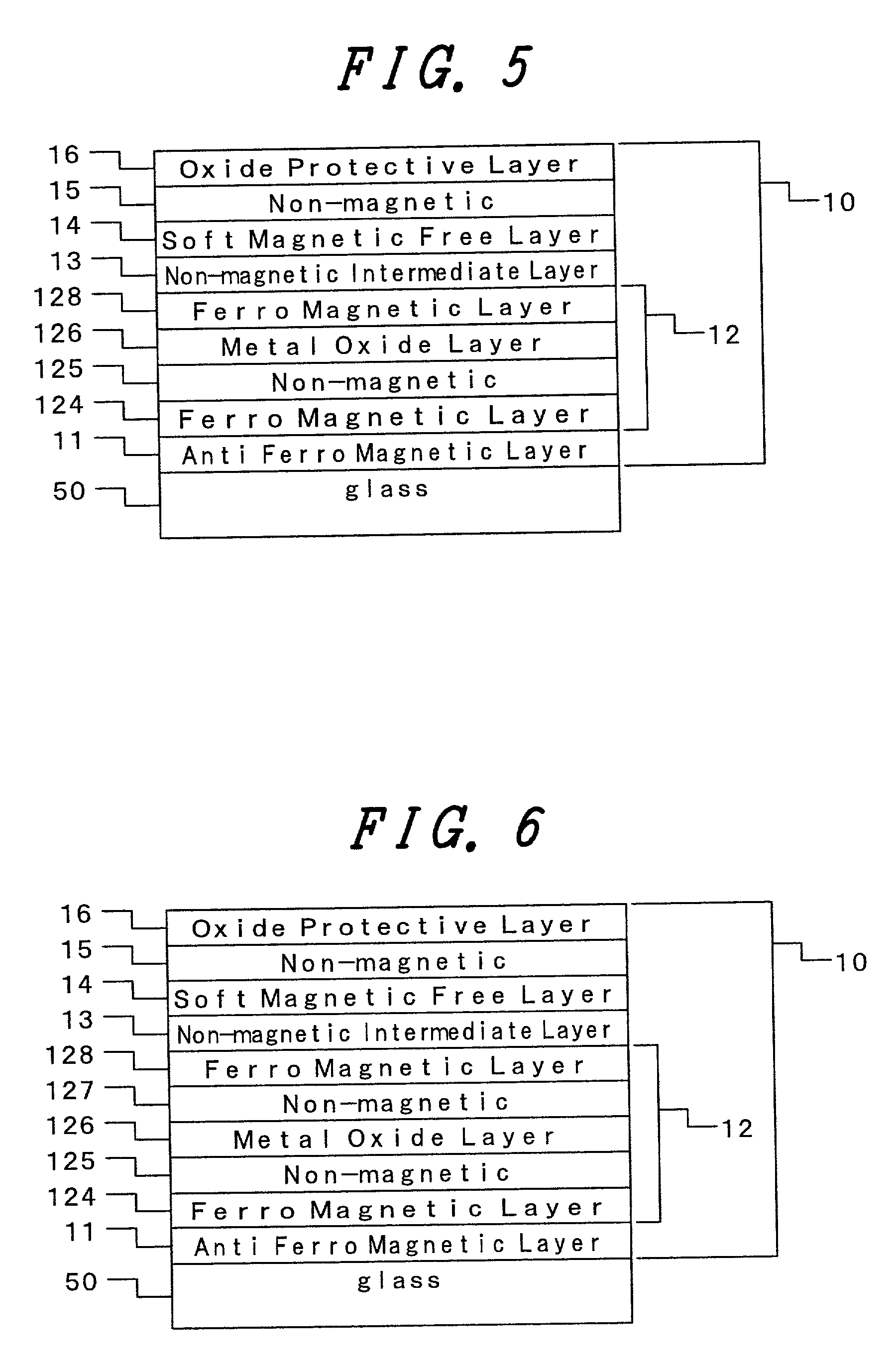
[0056] FIG. 5 illustrates an example of applying this invention to a spin-valve type magnetic head of another structure. The magnetoresistive lamination film 10 comprises a basic structure of laminating an anti-ferromagnetic film 11, a ferromagnetic pinned layer 12, a non-magnetic intermediate layer 13 and a soft magnetic free layer 14 laminated on a substrate 50 in which the ferromagnetic pinned layer 12 comprises a ferromagnetic layer 124, a non-magnetic high conductance oxidized stopper layer 125, a metal oxide layer 126 and a ferromagnetic layer 128. The metal oxide layer 126 of the ferromagnetic pinned layer is substantially oxidized entirely by the step exposed to the oxygen-containing atmosphere. In the same manner as in Example 3, by the provision of the oxide layer protective layer and the high conductance oxidized stopper layer, .DELTA.R, .DELTA.R / R and squareness ratio are improved.

example 4

[0057] Example 4

[0058] FIG. 6 illustrates an example of applying this invention to a spin-valve type magnetic head of a further different structure. The magnetoresistive lamination film 10 comprises a basic structure of laminating an anti-magnetic film 11, a ferromagnetic pinned layer 12, a non-magnetic intermediate layer 13 and a soft magnetic free layer 14 on a substrate 50, in which the ferromagnetic pinned layer 12 comprises a ferromagnetic layer 124, a non-magnetic high conductance oxidized stopper layer 125, a metal oxide layer 126, a non-magnetic high conductance oxidized stopper layer 127 and a ferromagnetic layer 128. The metal oxide layer 126 in FIG. 6 is entirely oxidized substantially by a step exposed to an oxygen-containing atmosphere in the same manner as in FIG. 5. By the provision of the oxide layer protective layer and the high conductance oxidized stopper layer, .DELTA.R, .DELTA.R / R and squareness ratio are improved.


PUM


Abstract

A magnetic head having a spin-valve type giant magnetoresistive film in which a non-magnetic high conductive oxidized stopper layer and an oxide protective layer with favorable magnetic characteristic for attaining high output, as well as a magnetic recording apparatus are provided, in which an additional non-magnetic high conductance oxidized stopper layer and an oxide film protective layer are laminated successively on the side of the surface adjacent to the soft magnetic free layer thereby increasing the giant magnetoresistive effect more than existent spin valve to prepare a high power magnetic head.

Description

[0001] 1. Field of the Invention[0002] This invention concerns a magnetoresistive element for reproducing magnetically recorded information and, more in particular, it relates to a magnetic reading / writing apparatus at high density using the magnetoresistive element for a reproducing head.[0003] 2. Related Prior Art[0004] Japanese Published Unexamined Patent Application No. Hei 4-358310 discloses a structure referred to as a spin-valve structure as one of heads using a giant magnetoresistive (GMR) effect.[0005] Japanese Published Unexamined Patent Application No. Hei 6-236527 describes a spin-valve type magnetoresistive sensor in which a back layer comprising a non-magnetic conductive material is disposed adjacent to a ferromagnetic layer.[0006] Physical Review Letters, vol. 75 (1995), pp 4306-4309 describes the dependence of the interlayer coupling field on the thickness of the Cu back layer in a Co / Cu / Co three layered film.[0007] Journal of Applied Physics, vol. 85 (1997), pp 6142...

Claims


Application Information

Patent Timeline
IPC IPC(8): G11B5/00G11B5/39
CPCB82Y10/00B82Y25/00G11B5/00G11B5/3903G11B2005/3996
Inventor HAYAKAWA, JUNHOSHIYA, HIROYUKIMEGURO, KENICHIWATANABE, KATSURO
Owner HITACHI GLOBAL STORAGE TECH JAPAN LTD
Learn More