
Information recording medium

a technology of information recording and information, applied in the field of information recording medium, can solve the problems of many problems that remain to be solved, the suppression of cross-erase is critical, and the 2.6 gbdvd-ram has not yet satisfied the requirements of users in the aspect of recording capacity

Inactive Publication Date: 2001-08-23
HITACHT MAXELL LTD
View PDF0 Cites 54 Cited by
  • Summary
  • Abstract
  • Description
  • Claims
  • Application Information

AI Technical Summary

Benefits of technology

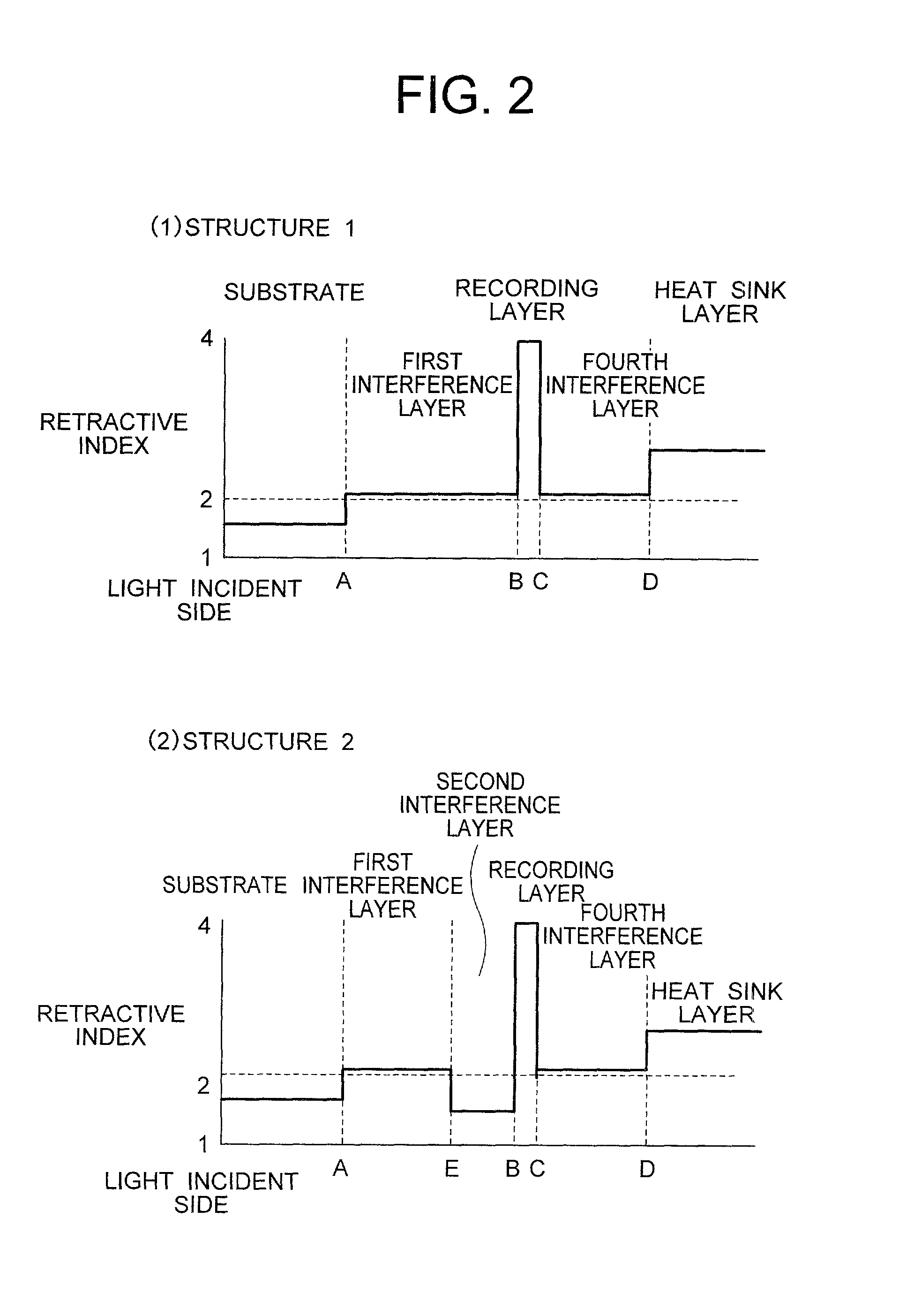
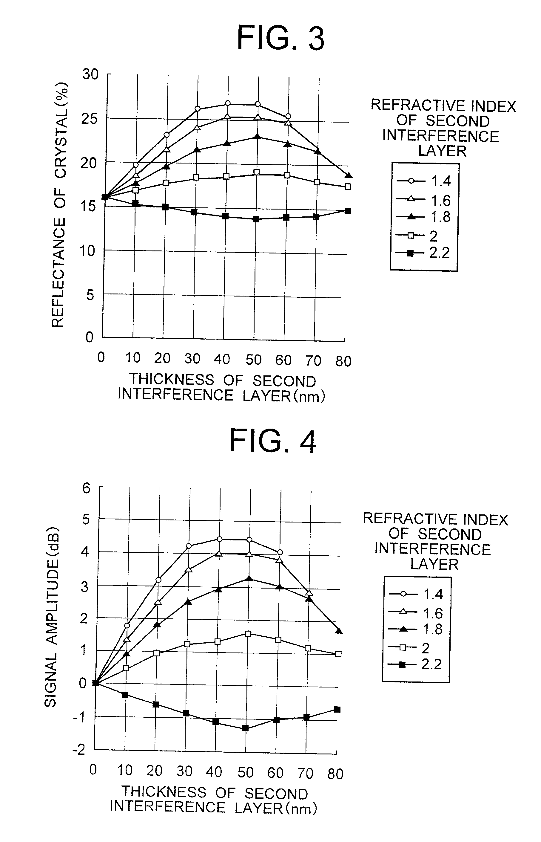
[0021] Reflectance can be improved when the refractive index of the first interference layer is greater than that of the second interference layer as will be explained in detail in the later-appearing embodiment.
[0040] Incidentally, the first interface layer, the second interface layer and the recording layer are generally extremely thin such as several nm. Therefore, there is the case where these layers do not always have a laminar shape but their films exist in spots in the island shape (formation of the thin films in the island shape). However, such spots of the films can be optically neglected as long as the distance between the island-like thin films is about {fraction (1 / 10)} of the wavelength of the laser beam, and the effects of the present invention are not lost by assuming that a layer having a mean film thickness of the island-like thin film exists. Even when the interface layer such as the second interface layer exists in the island form, for example, the effect of preventing the diffusion of each interference element into the recording layer can be obtained, though not sufficiently. The main object of the first interface layer is to prevent exfoliation occurring between the second interference layer and the recording layer. As to the first interface layer, therefore, there is no problem at all even when it exists in the island shape so long as the material used for the second interference layer does not easily diffuse into the recording layer.

Problems solved by technology

However, the 2.6 GBDVD-RAM has not yet satisfied sufficiently the requirements of users in the aspect of its recording capacity, and hopes have been laid on 4.7 GBDVD-RAM and 4.7 GBDVD-RW.
However, many problems remain yet to be solved in order to accomplish the 4.7 GBDVD-RAM.
Among others, suppression of cross-erase is a critical problem.
Generally, when a track pitch of an information recording medium is contracted to about 80% of a laser beam spot, leak of reproduction signals from adjacent information recording tracks occurs.
When the information recorded to the land is reproduced, for example, the reproduction signal from the information recorded to the groove leaks and the information recorded to the land cannot be reproduced accurately.
Therefore, it has been found that heat diffuses into an adjacent information recording track through the heat sink layer during recording of information and cross-erase is likely to occur (problem 1).
When the recording layer and the heat sink layer are spaced apart from each other to such an extent that cross-erase can be sufficiently suppressed (at least 65 nm when a laser wavelength is about 645 to about 660 nm), however, another problem develops in that reflectance drops due to the optical interference effect (problem 2).
However, since the recording layer and ZnS--SiO.sub.2 keep mutual contact in this method, the sulfur (S) element in the ZnS--SiO.sub.2 layer diffuses into the recording layer and invites the drop of reflectance when recording is repeatedly conducted thousands of times (problem 3).
Nonetheless, it has been clarified that when a high temperature humidification test is conducted in this method, exfoliation develops between the recording layer and the interface layer (problem 4).
It has been further clarified, however, that when the film thickness of the interface layer is below 5 nm, diffusion of the S atoms from the ZnS--SiO.sub.2 dielectric protective layer cannot be suppressed sufficiently (the occurrence of the problem 3).
When the technologies of the references 2 and 3 are combined, thin films of four layers, in all, exist on the laser beam incidence side of the recording layer, and the total number of thin films is undesirably great from the aspect of production.
Furthermore, the references 1, 2 and 3 do not sufficiently take cross-erase into consideration.
When the track pitch is narrowed, cross-erase develops depending on the film thickness of each layer (similar problem to the problem 1).
However, the problem occurs in that heat diffusing into the heat sink layer reaches the adjacent track and causes cross-erase.
Nonetheless, reflectance drastically drops in this construction.
When such a composition is used, the problem occurs in that the S atoms contained in the third interference layer diffuse into the recording layer during many-times over-write and lower reflectance.
However, these materials absorb readily light as described above, and they are likely to impede the multiple interference effect and to lower reflectance.
When land-groove recording is conducted as described in (6), cross-erase becomes a particular problem.
Even when the interface layer such as the second interface layer exists in the island form, for example, the effect of preventing the diffusion of each interference element into the recording layer can be obtained, though not sufficiently.

Method used


Image

  • Information recording medium
  • Information recording medium
  • Information recording medium

Examples


Embodiment Construction

[0057] The present invention will be explained in detail with reference to the following embodiments thereof.

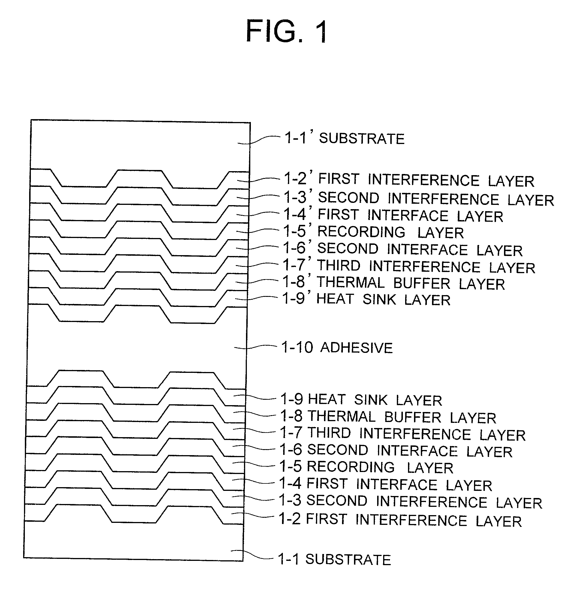
[0058] FIG. 1 shows a basic construction of an information recording medium according to the present invention. A first information recording member has a construction wherein a first interference layer 1-2, a second interference layer 1-3, a first interface layer 1-4, a recording layer 1-5, a second interface layer 1-6, a third interference layer 1-7, a thermal buffer layer 1-8 and a heat sink layer 1-9 are serially laminated over a substrate 1-1 provided with groove-like information recording tracks. Another information recording member having the same construction is bonded through an adhesive 1-10.

[0059] The substrate 1-1 uses a plastic transparent substrate such as a polycarbonate. Generally, the refractive index of such a transparent substrate is from about 1.5 to about 1.6. The first interference layer 1-2 must have optical characteristics such that its refractive inde...


PUM

PropertyMeasurementUnit
wavelengthaaaaaaaaaa
distanceaaaaaaaaaa
thicknessaaaaaaaaaa

Abstract

A high-density information recording medium free from lowering the reflectance by over-write of a large number of times and exfoliation defect in a structure for suppressing cross-erase. This medium includes, over a substrate having a groove shape, a recording layer, and three-layered thin films of a first interference layer, a second interference layer and an interface layer having mutually different compositions and disposed on a laser beam incidence side of the recording layer in order named from the laser beam incidence side. The first interference layer has a smaller refractive index and a larger thermal conductivity than the second interference layer, the interface layer is interposed between the second interference layer and the recording layer, and a distance between the first interference layer and the recording layer is greater than at least a groove depth.

Description

[0001] 1. Field of the Invention[0002] This invention relates to an information recording medium for recording information by irradiation of a laser beam. More particularly, this invention relates to optical disks capable of recording information and typified by phase change type optical disks such as DVD-RAM and DVD-RW, magneto-optic disks such as MD and MO and write-once type optical disks such as DVD-R.[0003] In this specification, the information recording medium is sometimes referred to as the "phase change optical disk", the "magneto-optic disk" or merely the "optical disk". However, the present invention can be applied to those types of information media that record information by generating heat by irradiating a laser beam and using this heat to cause a change in atomic configuration or a magnetic moment. For this reason, the present invention can be effectively applied to information recording media other than disk-like media, such as optical cards, without being particular...

Claims


Application Information

Patent Timeline
Patent Type & Authority Applications(United States)
IPC IPC(8): G11B7/007G11B7/24G11B7/24062G11B7/24079G11B7/257G11B7/258G11B7/2585
CPCG11B7/007G11B7/00718G11B7/24G11B7/243G11B7/2433G11B7/252G11B7/257G11B7/258G11B7/2585G11B7/259G11B7/2595G11B2007/24306G11B2007/24308G11B2007/2431G11B2007/24312G11B2007/24314G11B2007/24316G11B2007/25706G11B2007/2571G11B2007/25711G11B2007/25713G11B2007/25715G11B2007/25716Y10S430/146
Inventor MIYAMOTO, MAKOTOIKARI, YOSHIHIROFUCHIOKA, TAMOTSUWATANABE, HITOSHITAMURA, REIJIUSHIYAMA, JUNKOANDOO, KEIKICHIANZAI, YUMIKO
Owner HITACHT MAXELL LTD
Learn More