

Chemical liquid processing apparatus for processing a substrate and the method thereof
- Summary
- Abstract
- Description
- Claims
- Application Information
AI Technical Summary
Benefits of technology
Problems solved by technology
Method used
Image

Examples
first embodiment
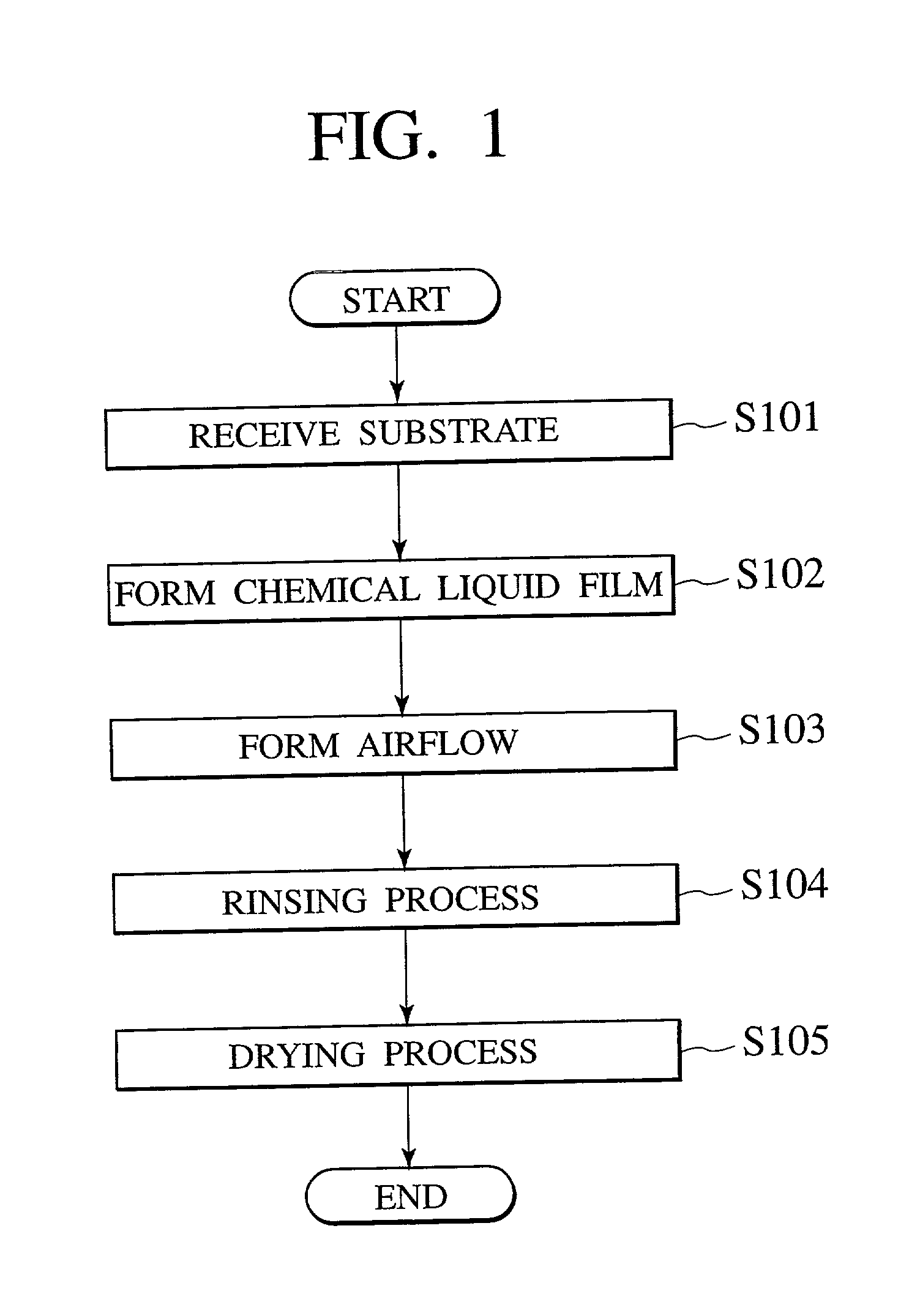
[0051] First, chemical liquid processing method according to the present invention is explained with reference to FIG. 1-4.
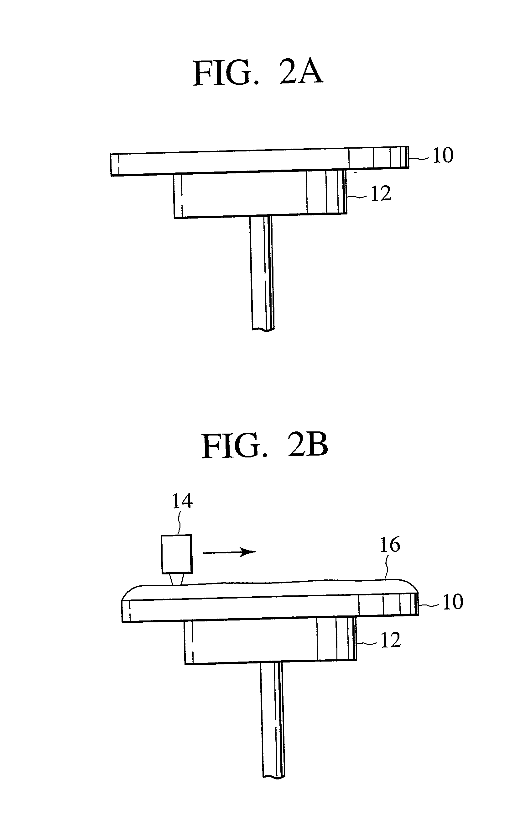
[0052] (1) First, as shown in FIG. 2A, the processing object substrate 10 which preparing step is finished is carried to the top of the substrate holding portion 12 by means of a transportation robot (not shown). And, the processing object substrate 10 is left from the transportation robot and received by the substrate holding portion 12. The processing object substrate 10 is fixed to the substrate holding portion 12 by sucking (S101).
[0053] (2) Next, as shown in FIG. 2B, chemical liquid 16 for processing a processing object film on the processing object substrate 10 is formed on the processing object substrate 10. Chemical liquid 16 is supplied from, for example, the chemical spouting nozzle 14 disposed above the processing object substrate 10. The chemical spouting nozzle 14 scans the processing object substrate 10 from an end of the processing object substrat...
second embodiment
[0071] Next, the chemical liquid processing according to the second embodiment of the present invention is described.
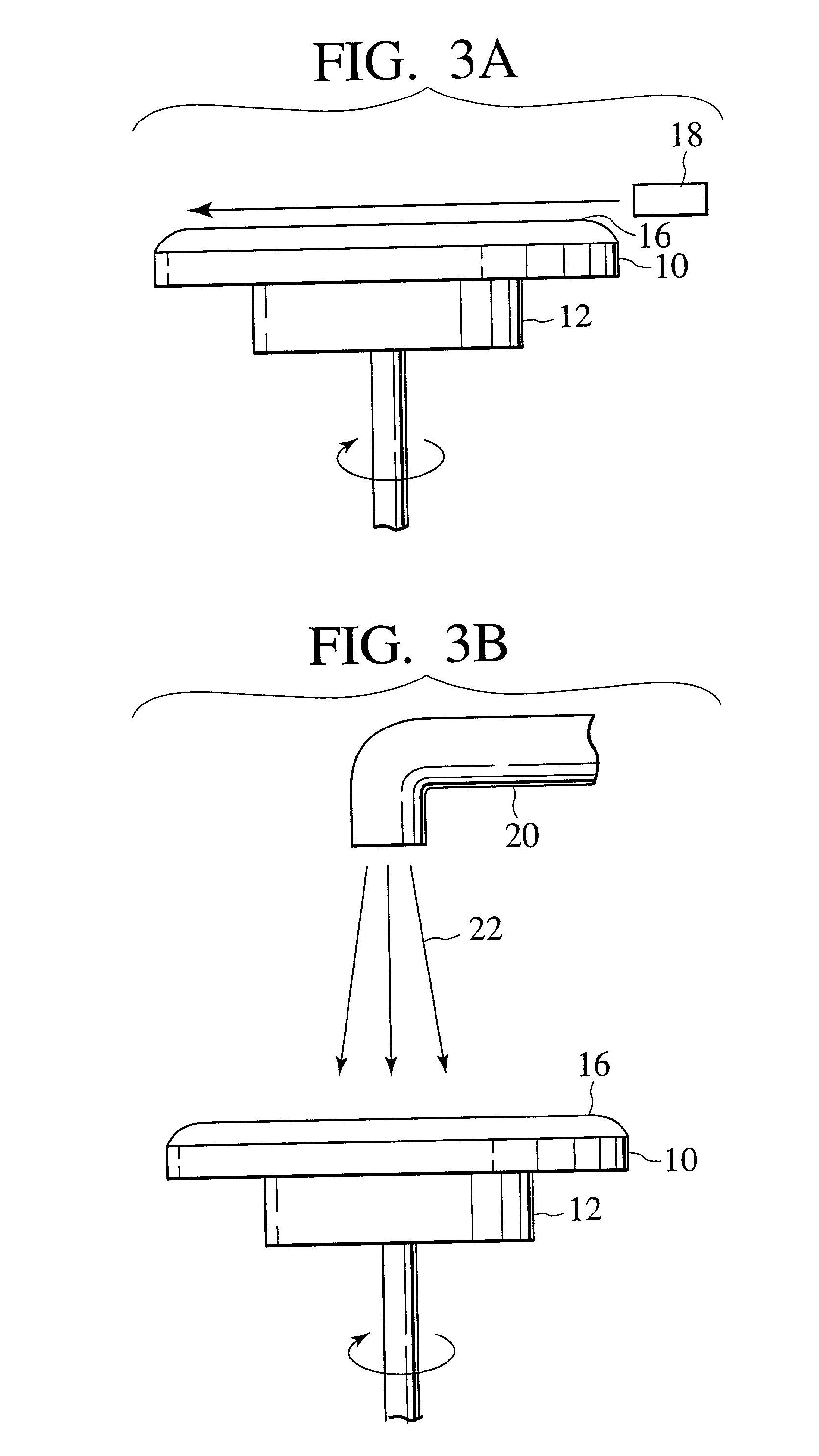
[0072] Although air flow is formed above the film of the chemical liquid 16 by supplying gas from the gas supply portion 18 disposed near the outer periphery of the processing object substrate 10 according to the first embodiment of the present invention, in the second embodiment of the present invention, air flow is formed by a rotation of a plate disposed above the film of the chemical liquid 16. Referring FIG. 1, FIG. 9.about.FIG. 11, the chemical liquid processing method according to the second embodiment of the present invention is explained below.
[0073] (1) First, as shown in FIG. 9A, the processing object substrate 10 which preparing step is finished is carried to the top of the substrate holding portion 12 by means of a transportation robot (not shown). Then, the processing object substrate 10 is left from the transportation robot and received by the substrate...
third embodiment
[0086] Next, the chemical liquid processing according to the third embodiment of the present invention is explained.
[0087] Although gas supplied above the film of the chemical liquid 16 by the gas supply portion 18 is restricted to only inactive gas such as nitrogen gas according to the first embodiment, in the third embodiment of the present invention, the other gas such as ozone is added. The third embodiment of the present invention is explained below referring the result of the experiment which the inventors performed.
[0088] First, reflection preventing film of 6 nm and resist film of 400 nm were formed successively on a semiconductor substrate 10, which was the processing object substrate. Then, after a latent image was formed on a resist film using an exposure device, baking was carried out at 130.degree. for 60 seconds.
[0089] Next, developing solution 16, which was the chemical liquid, was supplied to the top of a semiconductor substrate 10 so as to form film of the developin...
PUM
 Abstract
Description
Claims
Application Information