
Visible light response type phptocatalyst

a technology of photocatalysts and light sources, applied in the field of visible light response type photocatalysts, can solve the problems of insufficient performance, limited wavelength of available light, and inability to achieve the effect of reducing the number of spherical particles,

Inactive Publication Date: 2002-01-31
GUNMA PREFECTURE +1
View PDF0 Cites 37 Cited by
  • Summary
  • Abstract
  • Description
  • Claims
  • Application Information

AI Technical Summary

Benefits of technology

[0008] It is another object of the invention to provide a film with properties in which this visible light response type photocatalytic layer is provided on the base material surface, whereby the light decomposition properties are provided to the base material by means of visible light, self cleaning properties are provided, and hydrophily can be maintained for a long period of time.
[0016] Therefore, there is a possibility that the silicon oxide layer in the top layer hardly contributes to the photocatalytic function. However, if a titanium oxide layer is exposed, there may be problems with abrasion resistance, contamination resistance, water resistance, and chemical resistance. Thus, it is preferable that a silicon oxide layer is formed on a surface from a practical point of view, in order to avoid these problems. The silicon oxide provided in the top layer is 5 eV or more in band gap, and is transparent in visible and ultraviolet light. In addition, the thickness of the silicon oxide layer does not affect the light absorption properties of the visible light response type photocatalyst according to the present invention. However, it is preferable that it is not too thick in consideration of the diffusing properties of the positive hole produced by the titanium oxide. The film thickness is generally about 5 to 60 nm, preferably about 5 to 50 nm, and more preferably about 10 to 30 nm.
[0017] As described above, the top silicon oxide layer is not directly associated with the visible light response type photocatalytic function. However, in a case where a hydrophilic film is formed by employing the visible light response type photocatalyst according to the present invention, it is preferable that a silicon oxide layer is provided on the surface. This is considered to be not only because a hydroxy radical produced by water oxidization caused by the positive hole contributes to oxidization and decomposition of organic materials, but also because such a hydroxy radical is linked with Ti or Si on the film surface, and exists in a state such as "Ti--OH" or "Si--OH", and deeply contributes to provision of hydrophily. In addition, in comparing the stability between "Ti--OH" and "Si--OH" that contribute to hydrophily thereof, the stability of the "Si--OH" is remarkably high.
[0018] Therefore, when the "Si--OH" occurs once, it exists in this state for a long period of time, and the hydrophily of the base material surface can be maintained. In contrast, in the case of the "Ti--OH", it disappears within a short period of time, and the hydrophily of the base material surface cannot be obtained. Thus, in order to recover hydrophily of the base material surface, it requires light again, thereby forming "Ti--OH". Namely, even if the surface is placed for a long period of time in a state in which it is subjected to no light, it is preferable to provide a silicon oxide surface layer, in that there can be obtained a film capable of maintaining hydrophily for a long period of time.
[0024] In addition, according to the visible light response type photocatalyst of the present invention, a film having self cleaning properties can be obtained, the film providing an excellent effect that hydrophily can be maintained for a long period of time.
[0025] That is, utilizing the visible light response type photocatalyst according to the present invention can provide the photocatalytic function even in places where no ultraviolet rays are present (for example, in a vehicle chamber with ultraviolet ray cutting glass or under fluorescent light in a room). Thus, the photocatalyst according to the present invention can be utilized in places bright to the naked eye. In addition, the visible light response type photocatalyst according to the present invention also has a photocatalytic function under ultraviolet rays, and thus, its application range is extremely wide.

Problems solved by technology

However, the wavelength of available light is limited to an ultraviolet ray with its wavelength equal to or shorter than about 380 nm which is equal to a band gap (about 3.2 eV) of titanium oxide.
However, their performance has not been sufficient.
However, at present, these techniques are not practically established (for example, see Surface Chemistry, Volume 20, Second Issue, Pages 60 to 65 (1999)).
However, if a titanium oxide layer is exposed, there may be problems with abrasion resistance, contamination resistance, water resistance, and chemical resistance.
In contrast, in the case of the "Ti--OH", it disappears within a short period of time, and the hydrophily of the base material surface cannot be obtained.

Method used


Image

  • Visible light response type phptocatalyst
  • Visible light response type phptocatalyst
  • Visible light response type phptocatalyst

Examples


example 1

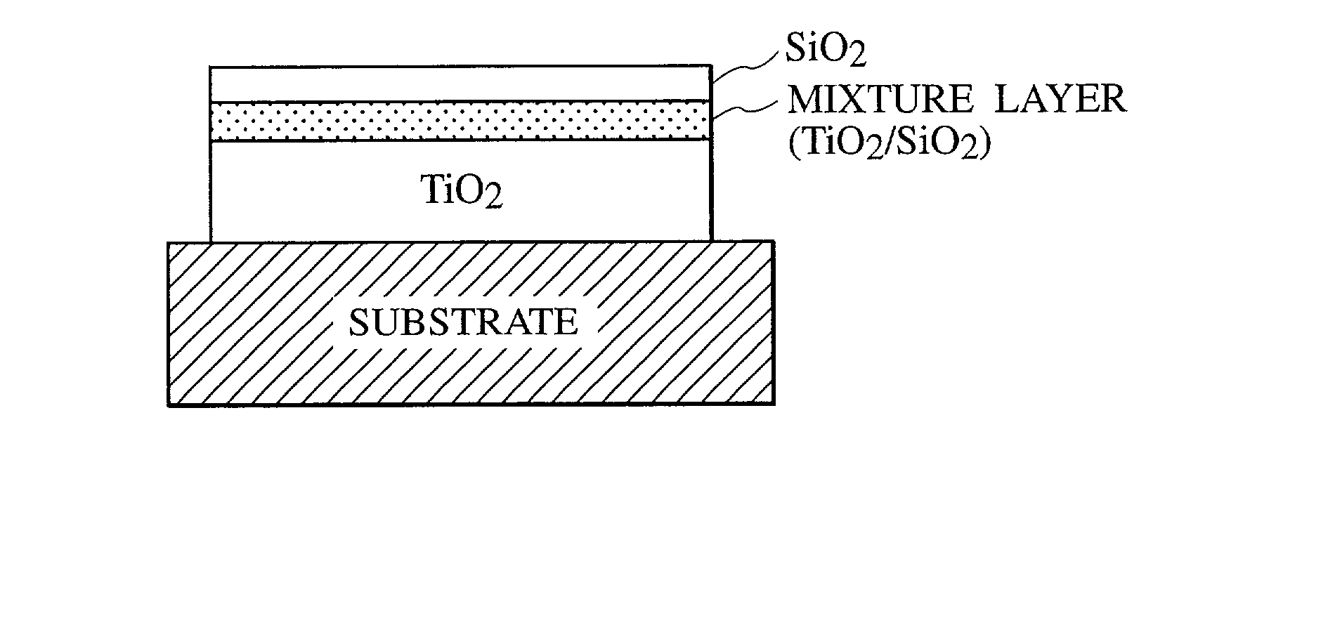
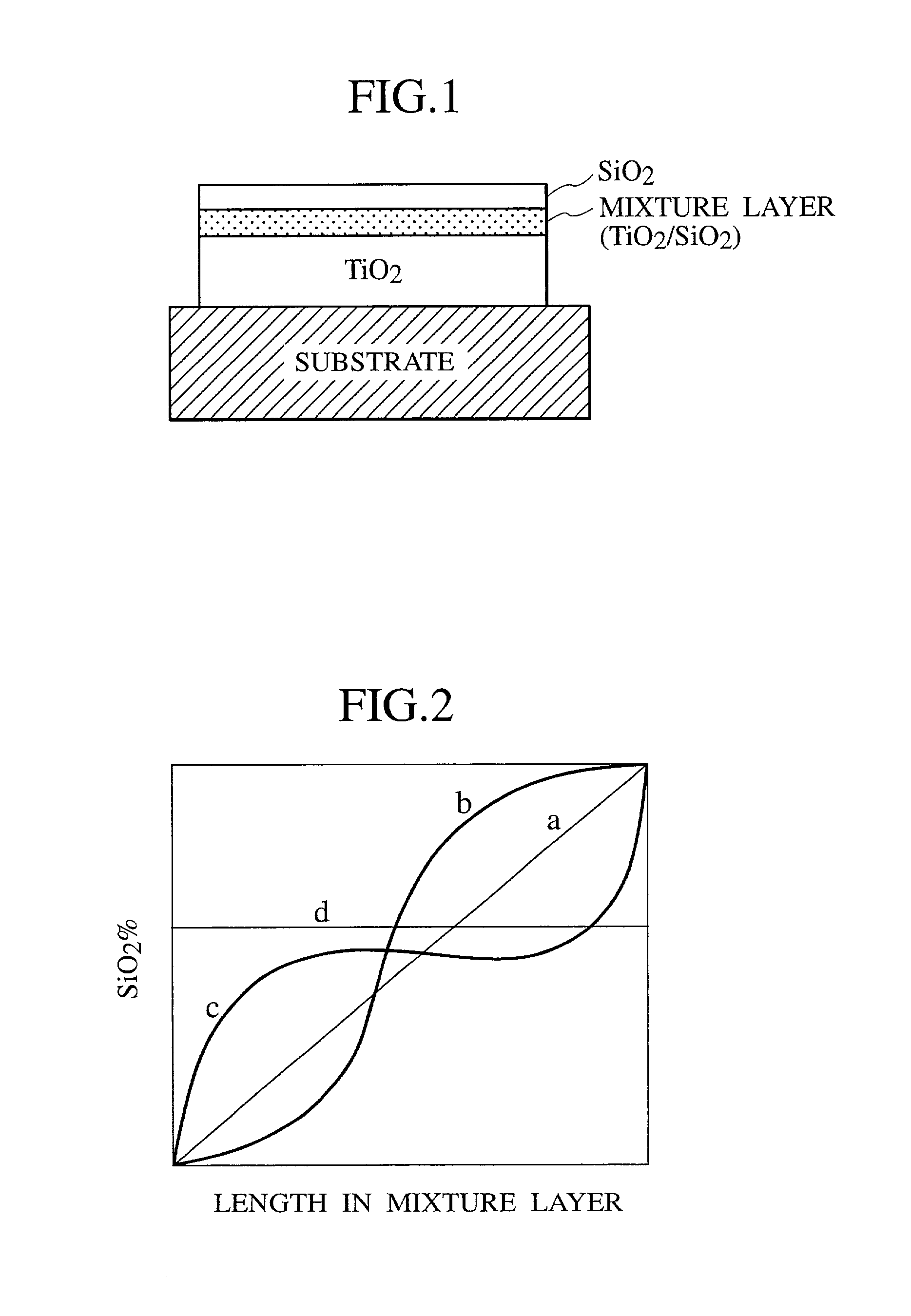
[0054] A 140 nm silicon oxide film being a barrier layer was vapor deposited onto a glass substrate by using a vacuum vapor deposition method, and then, a composite thin film including a titanium oxide layer, a mixture layer and a silicon oxide layer was produced. The film thickness of the respective layers was 300 nm, 20 nm, and 30 nm. The titanium oxide was of anatase type. The filming conditions are as shown in Table 1. The rate of the titanium oxide and the silicon oxide at the center of the mixture layer was 70:30 as a percentage by weight.

1 TABLE 1 TiO.sub.2 film Mixture film SiO.sub.2 film Vapor deposition 0.3 1.0 1.0 velocity (nm / sec) Oxygen introduction 2.67 .times. 10.sup.-2 2.67 .times. 10.sup.-2 2.67 .times. 10.sup.-2 pressure (Pa) Substrate 350 350 350 temperature (.degree. C.)

[0055] Polystyrene was spin coated onto this composite thin film, and light irradiation was carried out using nine types of wavelengths from 320 nm to 700 nm. Then, the catalytic activity of the v...

example 2

[0063] First, a composite thin film including a titanium oxide layer, a mixture layer, and a silicon oxide layer was directly produced on a glass substrate by using the vacuum vapor deposition method. The thickness of the respective layers was 200 nm, 100 nm, and 30 nm. The titanium oxide was of anatase type. The filming conditions are as shown in Table 2. The rate of the titanium oxide to silicon oxide at the center of the mixture layer was 70:30 as a percentage by weight.

2 TABLE 2 TiO.sub.2 film Mixture Film SiO.sub.2 film Vapor deposition 0.3 1.0 1.0 velocity (nm / sec) Oxygen introduction 2.67 .times. 10.sup.-2 2.67 .times. 10.sup.-2 2.67 .times. 10.sup.-2 pressure (Pa) Substrate 350 350 350 temperature (.degree. C.)

[0064] Then, a 0.1 wt. % dichloromethane solution of engine oil (castle motor oil), that is, a contamination source was applied to the obtained visible light response type photocatalyst film by way of dipping, and was dried, whereby a testing sample was produced.

[0065]...

example 3

CONVENTIONAL EXAMPLE 3

[0085] In accordance with the above steps 1) to 6), a sample was obtained when only a TiO.sub.2 layer (about 300 nm) was filmed on the glass substrate.


PUM

PropertyMeasurementUnit
Thicknessaaaaaaaaaa
Thicknessaaaaaaaaaa
Nanoscale particle sizeaaaaaaaaaa

Abstract

A present invention encompasses visible light response type photocatalyst having a titanium oxide layer, a mixture of titanium oxide and silicon oxide, and a silicon oxide layer, wherein these three layers are laminated in order onto a substrate.

Description

BACKGROUND OF THE INVENTION 1. Field of the Invention[0001] This invention relates to a visible light response type photocatalyst. More particularly, this invention relates to a film for forming a visible light response type photocatalyst layer onto a base material surface.[0002] 2. Description of Related Art[0003] Conventionally, an anatase type titanium oxide has attracted attention as a photocatalyst. When an ultraviolet ray with its wavelength shorter than 380 nm is irradiated to this catalyst, it is known as a "Honda-Fujishima effect", to cause an oxidization and reduction reaction such as water decomposition, for example. In addition, based on this effect, a variety of products are produced, where a titanium oxide film or thin film is formed on a base material surface, some of which are commercially available.[0004] The photocatalytic properties of this titanium oxide can induce an oxidization and decomposition reaction by absorbing a slight amount of ultraviolet rays included...

Claims


Application Information

Patent Timeline
IPC IPC(8): C03C17/34B01J21/08B01J35/00B01J35/02B01J37/02C09K3/00
CPCB01J35/002B01J35/004B01J37/0244Y10T428/24975C03C2217/71Y10T428/265C03C17/3417B01J35/30B01J35/39B01J21/06B01J35/00B01J35/56
Inventor MIYASHITA, KIYOSHIKURODA, SHINICHIUBUKATA, TSUTOMUENOMOTO, MINORU
Owner GUNMA PREFECTURE
Learn More