
System for using rapid acquisition spreading codes for spread-spectrum communications

a spread-spectrum communication and spreading-spectrum technology, applied in the field of systems for using rapid acquisition spreading codes for spreading-spectrum communications, can solve the problems of inability to track the maximum of f(t), inability to know the correct pilot spreading code, and excessive time taken

Inactive Publication Date: 2002-02-21
INTERDIGITAL TECH CORP
View PDF99 Cites 31 Cited by
  • Summary
  • Abstract
  • Description
  • Claims
  • Application Information

AI Technical Summary

Benefits of technology

[0121] Although the described embodiment uses different spread-spectrum bandwidths centered around a carrier for the transmit and receive spread-spectrum channels, the present method is readily extended to systems using multiple spread-spectrum bandwidths for the transmit channels and multiple spread-spectrum bandwidths for the receive channels. Alternatively, because spread-spectrum communication systems have the inherent feature that one user's transmission appears as noise to another user's despreading receiver, an embodiment may employ the same spread-spectrum channel for both the transmit and receive path channels. In other words, uplink and downlink transmissions can occupy the same frequency band. Furthermore, the present method may be readily extended to multiple CDMA frequency bands, each conveying a respectively different set of messages, uplink, downlink or uplink and downlink.
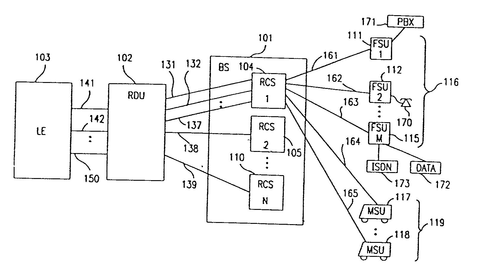
[0130] The SU encodes voice data with techniques such as ADPCM at 32 kbs or lower rates, and detects voiceband data or FAX with rates above 4.8 kbs to modify the traffic channel (bearer rate modification) for unencoded transmission. Also, A-law, u-law or no compounding of the signal may be performed before transmission. For digital data, data compression techniques, such as idle flag removal, may also be used to conserve capacity and minimize interference. The transmit power levels of the radio interface between RCS 104 and SUs 111, 112, 115, 117 and 118 are controlled using two different closed loop power control methods. The automatic forward power control (AFPC) method determines the downlink transmit power level, and the automatic reverse power control (ARPC) method determines the Uplink transmit power level. The logical control channel by which SU 111 and RCS 104, for example, transfer power control information operates at least a 16 kHz update rate. Other embodiments may use a faster or slower update rate, for example 64 kHz. These algorithms ensure that the transmit power of a user maintains an acceptable bit-error rate (BER), maintains the system power at a minimum to conserve power and maintains the power level of all SUs 111, 112, 115, 117 and 118 received by RCS 104 at a nearly equal level. In addition, the system uses an optional maintenance power control method during the inactive mode of a SU. When SU 111 is inactive or powered-down to conserve power, the unit occasionally activates to adjust its initial transmit power level setting in response to a maintenance power control signal from RCS 104. The maintenance power signal is determined by the RCS 104 by measuring the received power level of SU 111 and present system power level and, from this, calculates the necessary initial transmit power. The method shortens the channel acquisition time of SU 111 to begin a communication. The method also prevents the transmit power level of SU 111 from becoming too high and interfering with other channels during the initial transmission before the closed loop power control reduces the transmit power.
[0132] RCS 104, SU 111 and RDU 102 may incorporate system redundancy of system elements and automatic switching between internal functional system elements upon a failure event to prevent loss or drop-out of a radio link, power supply, traffic channel or group of traffic channels.
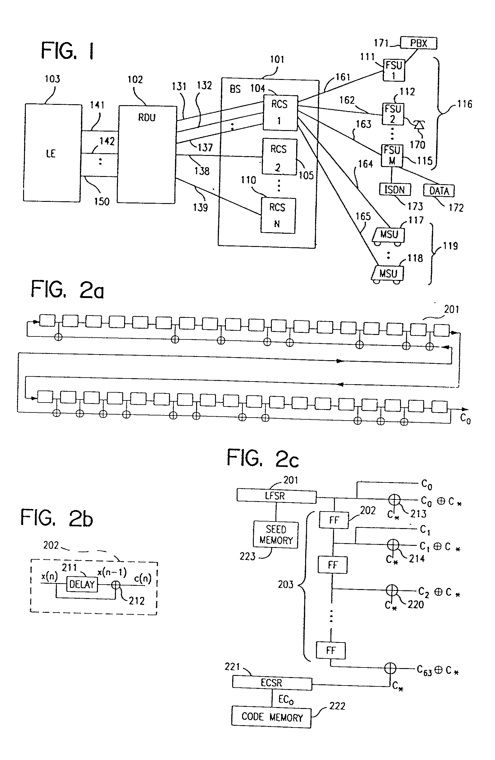
[0159] The present invention includes a method to increase the number of available seeds for use in a CDMA communication system by recognizing that certain cyclic shifts of the previously determined code sequences maybe used simultaneously. The round trip delay for the cell sizes and bandwidths of the present invention are less than 3000 chips. In one embodiment of the present invention, sufficiently separated cyclic shifts of a sequence can be used within the same cell without causing ambiguity for a receiver attempting to determine the code sequence. This method enlarges the set of sequences available for use. By implementing the tests previously described, a total of 3879 primary seeds were determined through numerical computation. These seeds are given mathematically as:.delta..sup.n modulo h(x) Equation (5)
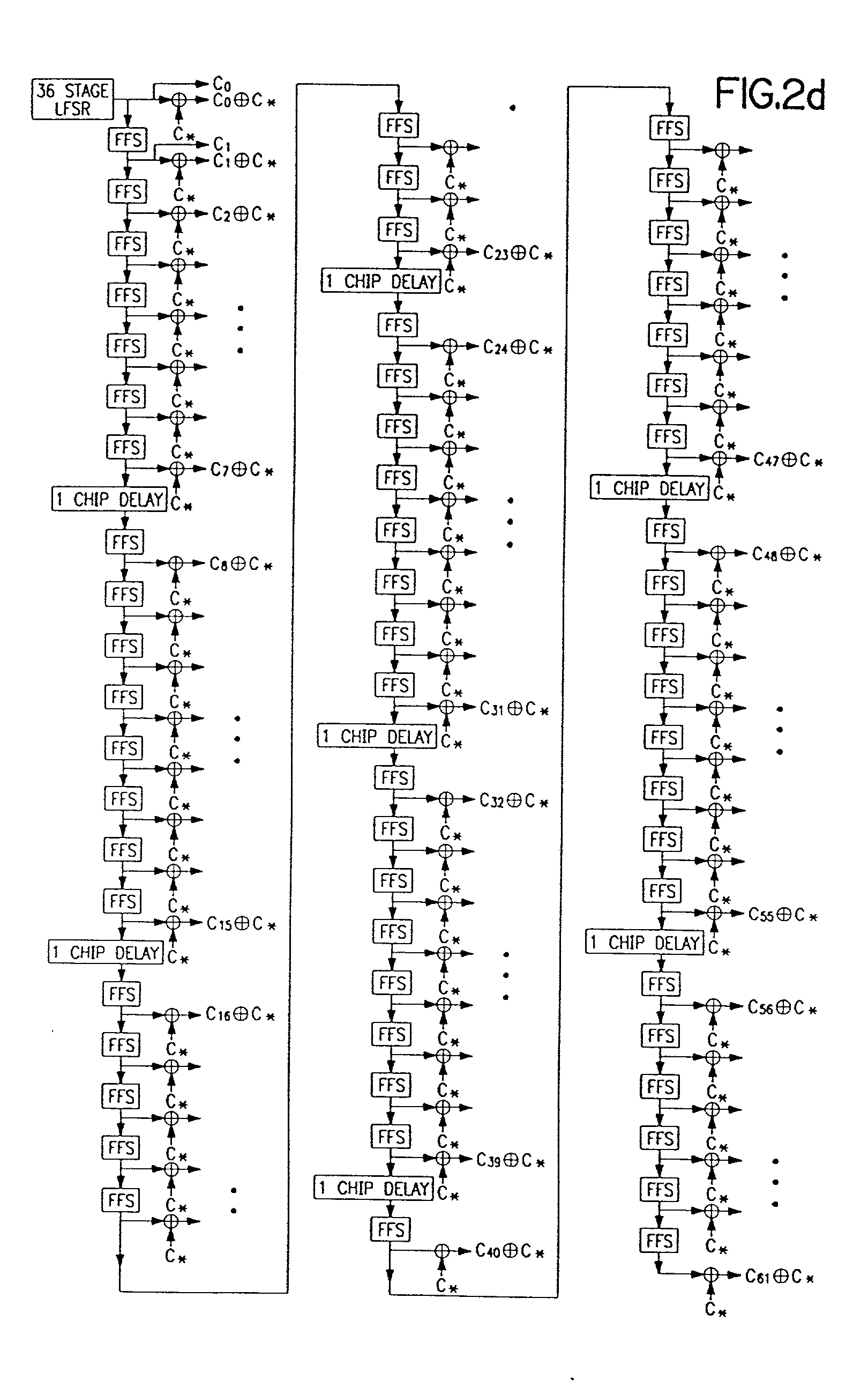
[0184] For global codes, the seed values for the 36 bit shift register are chosen to avoid using the same code, or any cyclic shift of the same code, within the same geographical area to prevent ambiguity or harmful interference. No assigned code is equal to, or a cyclic shift of, a global code.

Problems solved by technology

However, in multipath fading channels, the receiver despread code waveform can have a number of local maxima, especially in a mobile environment.
The frequency response characteristic of f(t) and the maximum of this characteristic can change rather quickly making it impractical to track the maximum of f(t).
The time required for the base station to acquire the access signal of a SU that has gone "off-hook" contributes to the delay between the SU going off-hook and the receipt of a dial tone from the PSTN.
The SU cold acquisition algorithm is used by the SU CDMA modem when it is first powered up, and therefore has no knowledge of the correct pilot spreading code phase, or when an SU attempts to reacquire synchronization with the incoming pilot signal but has taken an excessive amount of time.
Thus, it maybe problematical to adjust the phase .tau.' based on measurements of the signal f(t+.tau.).
A disadvantage of the functional is that it is ill-defined because the integrals are unbounded when noise is present.

Method used


Image

  • System for using rapid acquisition spreading codes for spread-spectrum communications
  • System for using rapid acquisition spreading codes for spread-spectrum communications
  • System for using rapid acquisition spreading codes for spread-spectrum communications

Examples


Embodiment Construction

[0117] I. General System Description

[0118] The system of the present invention provides local-loop telephone service using radio links between one or more base stations and multiple remote subscriber units. In the exemplary embodiment, a radio link is described for a base station communicating with a fixed subscriber unit (FSU), but the system is equally applicable to systems including multiple base stations with radio links to both FSUs and mobile subscriber units (MSUs). Consequently, the remote subscriber units are referred to herein as subscriber units (SUs).

[0119] Referring to FIG. 1, base station (BS) 101 provides call connection to a local exchange (LE) 103 or any other telephone network switching interface, such as a private branch exchange (PBX) and includes a radio carrier station (RCS) 104. One or more RCSs 104, 105, 110 connect to a radio distribution unit (RDU) 102 through links 131, 132, 137, 138, 139, and RDU 102 interfaces with LE 103 by transmitting and receiving ca...


PUM


Abstract

A multiple access, spread-spectrum communication system processes a plurality of information signals received by a radio carrier station over telecommunication lines for simultaneous transmission over a radio frequency channel as a code-division-multiplexed signal to a group of subscriber units. The radio carrier station receives a call request signal that corresponds to a telecommunication line information signal, and a user identification signal that identifies a user to receive the call. The radio carrier station includes a plurality of CDMA modems, one of which provides a global pilot code signal. The modems provide message code signals synchronized to the global pilot signal. Each modem combines an information signal with a message code signal to provide a code division multiplexed signal. The RCS includes a system channel controller is coupled to receive a remote call. A radio frequency transmitter is connected to all of the modems to combine the code division multiplexed processed signals with the global pilot code signal to generate a code division multiplexed signal. The transmitter also modulates a carrier signal with the code division multiplexed signal and transmits the modulated carrier signal through a radio frequency communication channel to the subscriber units. Each subscriber unit includes a CDMA modem which is also synchronized to the global pilot signal. The CDMA modem despreads the code division multiplexed signal and provides a despread information signal to the user. The system includes a closed loop power control system for maintaining a minimum system transmit power level for the radio carrier station and the subscriber units, and system capacity management for maintaining a maximum number of active subscriber units for improved system performance.

Description

[0001] This application is a continuation-in-part to U.S. patent application Ser. No. 08 / 956,740 filed on Oct. 23, 1997; which is a continuation of U.S. patent application Ser. No. 08 / 669,775 filed on Jun. 27, 1996 which issued on Aug. 25, 1998 as U.S. Pat. No. 5,799,010; which is a continuation-in-part to U.S. Provisional Application No. 60 / 000,775 filed on Jun. 30, 1995. This application is also a continuation-in-part to U.S. patent application Ser. No. 09 / 003,104 filed on Jan. 6, 1998; which is a continuation of U.S. patent application Ser. No. 08 / 670,162 filed on Jun. 27, 1996 which issued on Nov. 24, 1998 as U.S. Pat. No. 5,841,768. This application is also a continuation-in-part to U.S. patent application Ser. No. 09 / 304,286 filed on May 3, 1999; which is a continuation of U.S. patent application Ser. No. 08 / 671,068 filed on Jun. 27, 1996 which issued on Aug. 30, 1999 as U.S. Pat. No. 5,940,382. This application is also a continuation-in-part to U.S. patent application Ser. No...

Claims


Application Information

Patent Timeline
Patent Type & Authority Applications(United States)
IPC IPC(8): G06F13/374H03H17/02H03H17/06H04B1/69H04B1/707H04B7/005H04B7/26H04J13/00H04J13/02H04J13/04H04L1/00H04L5/14H04L25/02H04L27/00H04L27/20H04L27/233H04N1/333
CPCG06F13/374Y02B60/1228H03H17/06H03H21/0018H03H2218/06H04B1/7075H04B1/70752H04B1/70753H04B1/70755H04B1/70758H04B1/708H04B1/7085H04B1/7093H04B1/7115H04B1/712H04B7/2628H04B7/2637H04B7/264H04B2201/70701H04B2201/70702H04B2201/70703H04B2201/70707H04B2201/7071H04J13/004H04J13/10H04J13/107H04L1/004H04L5/1446H04L25/0212H04L27/206H04L27/2332H04L2027/003H04L2027/0053H04W52/08H04W52/146H04W52/24H04W52/26H04W52/322H04W52/325H04W52/343H04W52/36H04W52/367H04W52/44H04W52/50H04W52/52H04W52/54H04W52/60H03H17/0226Y02D10/00
Inventor OZLUTURK, FATIH M.LOMP, GARY R.
Owner INTERDIGITAL TECH CORP
Learn More