

Information recording method
a technology of information recording and polymer thin film, which is applied in the field of information recording methods, can solve the problems of slow velocity in the morphological changes of polymeric thin film, and achieve the effect of greatly increasing the velocity of the morphological changes of azobenzene-based polymeric thin film
Inactive Publication Date: 2002-03-21
NAT INST OF ADVANCED IND SCI & TECH
View PDF6 Cites 23 Cited by
- Summary
- Abstract
- Description
- Claims
- Application Information
AI Technical Summary
Benefits of technology
[0005] In view of the above described problems in the information recording method by irradiating a thin film of a polymeric compound having a chemical structure of azobenzene with a light beam relative to the velocity of the morphological changes caused in the polymeric thin film, the present invention has an object to provide an improvement by which the velocity of the morphological changes in the azobenzene-based polymeric thin film can be greatly increased.
Problems solved by technology
The most serious problem encountered in the development of this information recording method by utilizing the above mentioned unique phenomenon is the slow velocity in the morphology changes of the polymeric thin film.
Method used
View moreImage
Smart ImageViewing Examples

Examples
example 2
[0036] The experimental procedure was substantially the same as in Example 1 excepting for the replacement of the linear-polarized light for the bias light with a circular-polarized light.
[0037] FIG. 5 is a graph showing the height difference between recesses or pits and raises in the thus formed rugged surface as a function of the irradiance by the bias light. As is shown in this graph, the height difference, which was 5.8 nm in the absence of the bias light, was increased approximately linearly as the irradiance by the bias light was increased reaching 28.9 nm when the irradiance was 31.2 mW / cm.sup.2, i.e. about 5 times of the height difference in the absence of the bias light.
Login to View More PUM
 Abstract
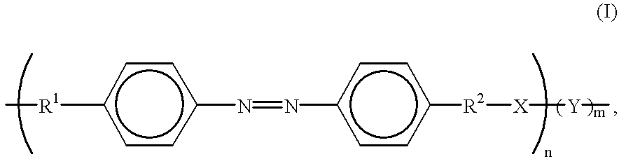
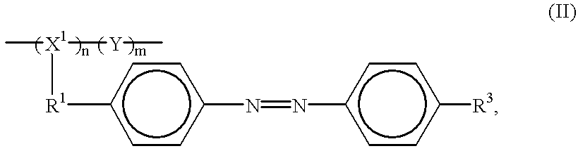
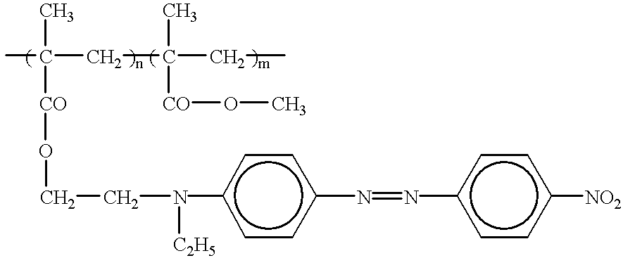
Disclosed is an improvement in an optical information recording method by utilizing a unique phenomenon in which, when a thin film of a polymeric compound having a structure of azobenzene is irradiated spotwise with a light beam of a specified wavelength, a pattern of rugged surface with recesses and raises is resulted by the migration of the polymer molecules from the strongly irradiated area to the weakly irradiated area. The improvement has an object to increase the photosensitivity of this phenomenon by simultaneously irradiating the polymeric thin film with a second or bias light beam of a larger cross section to envelop the irradiation spot by the first or writing light beam.
Description
[0001] The present invention relates to an improvement in an information recording method. More particularly, the invention relates to an improvement in an optical information recording method in which a thin film of a light-sensitive polymeric compound having a chemical structure of azobenzene is irradiated with a light beam of a specified wavelength to produce a surface pattern with recesses and raises.[0002] It is reported in Applied Physics Letters, volume 66 (1995), pages 136-138 and pages 1166-1168 that, when a thin film of a polymeric compound having a chemical structure of azobenzene is irradiated with a light beam of a wavelength matching with the wavelength of the absorption band of the polymeric compound, such as the argon laser beam of 515-458 nm wavelengths, movement of the polymer chains is induced corresponding to the geometrical profile of the laser beam and polarization of the light to produce a surface pattern with recesses and raises.[0003] This phenomenon is caus...
Claims
Login to View More Application Information
Patent Timeline
 IPC IPC(8): G03C1/73G02B5/18G03H1/02G03H1/04G11B7/0045G11B7/125
CPCG11B7/0045
InventorFUKUDA, TAKASHIMATSUDA, HIROOSUMARU, KIMIOKIMURA, TATSUMIKATO, MASAO
OwnerNAT INST OF ADVANCED IND SCI & TECH