
Reduction resistant thermistor, method of production thereof, and temperature sensor

a thermistor and resistance technology, applied in the direction of non-metal conductors, oxide conductors, conductors, etc., can solve the problems of oxidizing the metal case, and affecting the performance of the thermistor

Inactive Publication Date: 2002-03-28
NIPPON SOKEN +1
View PDF0 Cites 13 Cited by
  • Summary
  • Abstract
  • Description
  • Claims
  • Application Information

AI Technical Summary

Benefits of technology

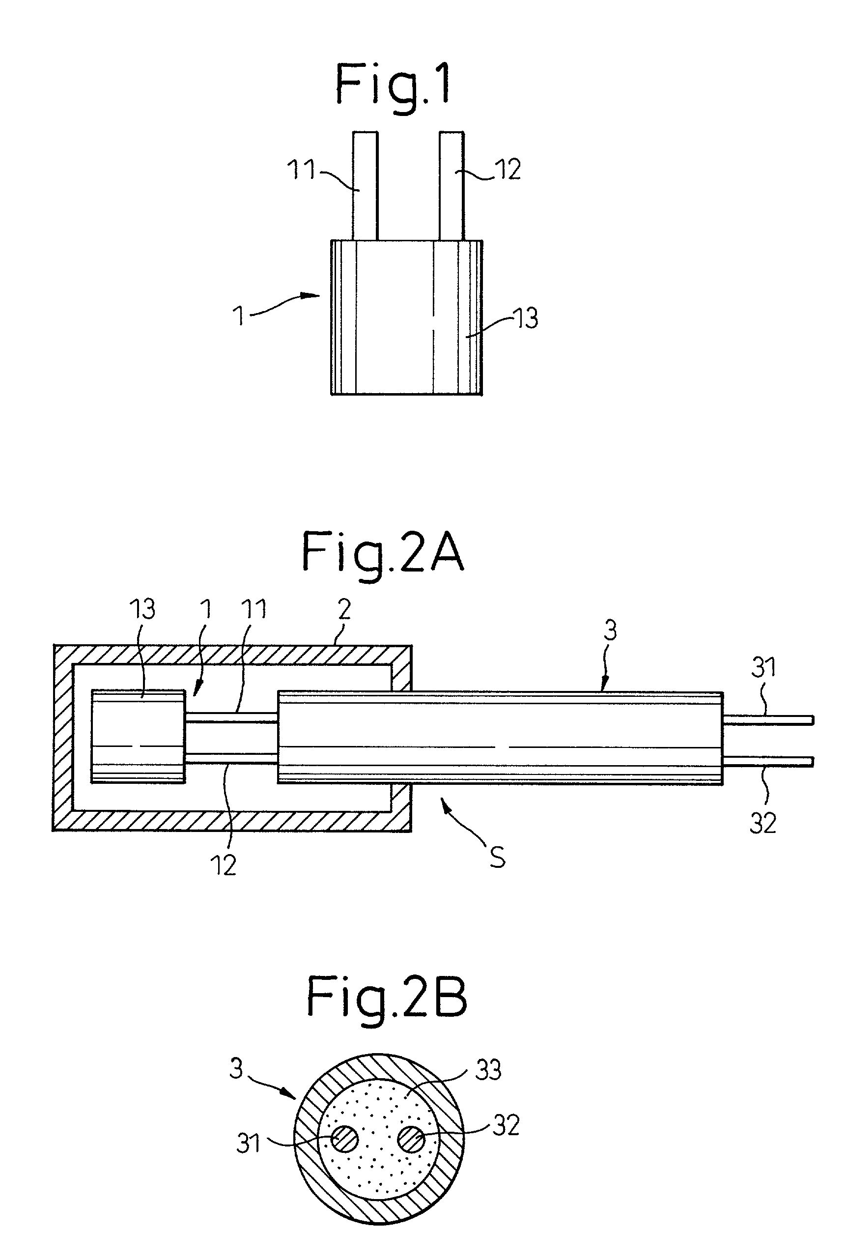
[0008] On the other hand, Japanese Unexamined Patent Publication (Kokai) No. 9-69417 discloses to form a metal case from a special metal material, for example, an alloy mainly comprised of Ni--Cr--Fe, so as to suppress changes in the atmosphere in the case and reduce the change in resistance of the thermistor. Making the metal case from a special metal material, however, results in an increase in the cost of materials and the cost of processing. Further, the problem of the change in resistance when the thermistor itself is exposed to a reducing atmosphere remains unchanged.
[0010] An object of the present invention is to provide at a low cost a reduction resistant thermistor free from major changes in resistance even if exposed to a reducing atmosphere and having a high accuracy and superior stability of resistance.

Problems solved by technology

When the emission becomes a high temperature of about 900.degree. C., however, the metal case oxidizes due to the heat of the high temperature emission and the inside of the metal case easily becomes a reducing atmosphere.
Therefore, there was the problem that the oxides comprising the thermistor were subjected to a reducing action and changed in resistance.
During use of a temperature sensor, however, if holes form in the metal case or the case warps etc. and therefore emission enters the case and the thermistor is exposed to a reducing atmosphere, the resistance is liable to change.
In this way, the problems have not been completely solved by heat aging.
Further, there was the disadvantage that the number of production steps increased and therefore the temperature sensor became higher in cost.
Making the metal case from a special metal material, however, results in an increase in the cost of materials and the cost of processing.
Further, the problem of the change in resistance when the thermistor itself is exposed to a reducing atmosphere remains unchanged.
If the mean particle size of the thermistor material is 1.0 .mu.m or more, it is difficult to increase the mean sintered particle size and obtain the above desired range.
If the mean sintered particle size of the metal oxide sintered body is smaller than 3 .mu.m, the grain boundaries increase, the oxygen easily migrates, and reduction of the thermistor in a reducing atmosphere cannot be suppressed.
Here, La is not used as M1 since it has a high hygroscopicity, reacts with the moisture in the atmosphere to form an unstable hydroxide, and causes problems such as breakage of the thermistor.
When using the composite oxide (M1 M2)O.sub.3 alone as the thermistor material, however, the stability of the resistance is insufficient.
Further, the resistance in the high temperature region tends to become lower.

Method used


Image

  • Reduction resistant thermistor, method of production thereof, and temperature sensor
  • Reduction resistant thermistor, method of production thereof, and temperature sensor
  • Reduction resistant thermistor, method of production thereof, and temperature sensor

Examples


example 2

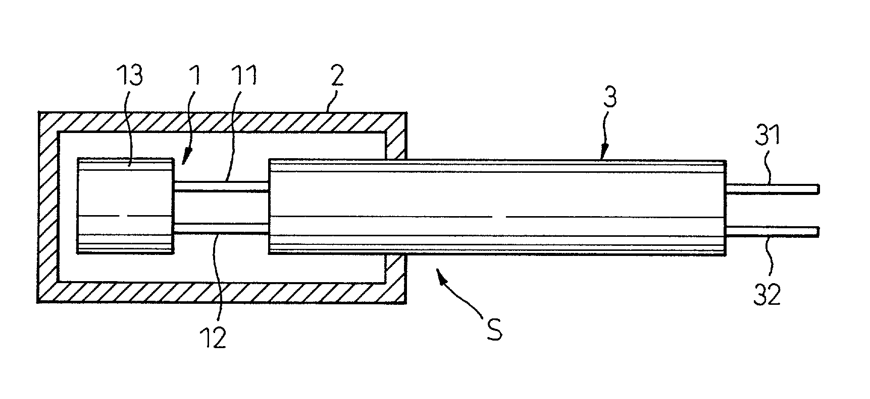
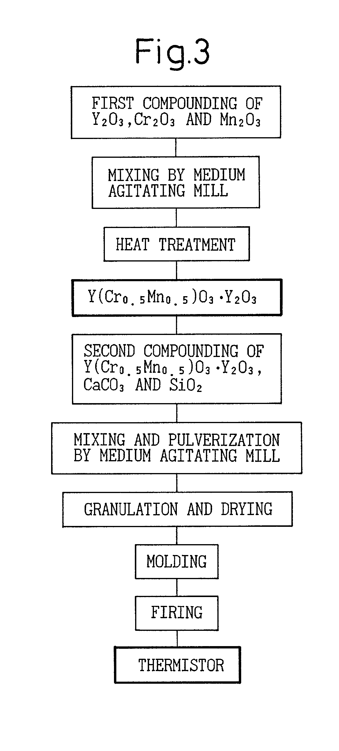
[0097] In Example 2, a thermistor comprised of a mixed sintered body of the same composition as Example 1, that is, aY(Cr.sub.0.5Mn.sub.0.5)O.sub-.3.multidot.bY.sub.2O.sub.3 (a=0.38, b=0.62) was prepared by changing just the firing conditions in the firing step in the production process shown in FIG. 3. The same method was used to obtain, granulate, dry, and shape a thermistor material of a mean particle size of 0.2 .mu.m, then the firing conditions in the firing step were changed and the body fired in the atmosphere at 1550.degree. C. for 6 hours to obtain a thermistor comprised of a mixed sintered body having a mean sintered particle size of 10 .mu.m.

[0098] A temperature sensor incorporating this thermistor was prepared and evaluated in the same way as in Example 1. The maximum rate of change of resistance .DELTA.R, the temperature accuracy after a high temperature continuous durability test, and the initial temperature accuracy are shown in Table 1. As shown in Table 1, it could ...

example 3

[0099] In Example 3, a thermistor comprised of a mixed sintered body of the same composition as Example 1, that is, aY(Cr.sub.0.5Mn.sub.0.5)O.sub-.3.multidot.bY.sub.2O.sub.3 (a=0.38, b=0.62) was prepared by changing just the firing conditions in the firing step in the production process shown in FIG. 3. The same method was used to obtain, granulate, dry, and shape a thermistor material of a mean particle size of 0.2 .mu.m, then the firing conditions in the firing step were changed and the body fired in the atmosphere at 1600.degree. C. for 6 hours to obtain a thermistor comprised of a mixed sintered body having a mean sintered particle size of 20 .mu.m.

[0100] A temperature sensor prepared using this thermistor was evaluated in the same way as in Example 1. The maximum rate of change of resistance .DELTA.R, the temperature accuracy after a high temperature continuous durability test, and the initial temperature accuracy are shown in Table 1. As shown in Table 1, it could be confirmed...

example 4

[0101] Based on the process of production shown in FIG. 4, a thermistor comprised of a mixed sintered body of the same composition as Example 1, that is, aY(Cr.sub.0.5Mn.sub.0.5)O.sub.3.multidot.bY.sub.2O.sub.3 (a=0.38, b=0.62) was prepared. Example 4 differs from Examples 1 to 3 in the point of use of sol particles of oxides of the metal elements forming the mixed sintered body, that is, sol particles of Y.sub.2O.sub.3, sol particles of Cr.sub.2O.sub.3, and sol particles of Mn.sub.2CO.sub.3 as starting materials.

[0102] In the first compounding step, Y.sub.2O.sub.3 sol particles, Cr.sub.2O.sub.3 sol particles, and Mn.sub.2CO.sub.3 sol particles each having a purity of at least 99.9% and a mean particle size of not more than 0.1 .mu.m and a sintering aid of CaCO.sub.3 sol particles were prepared as starting materials. The Y.sub.2O.sub.3 sol particles, Cr.sub.2O.sub.3 sol particles, and Mn.sub.2CO.sub.3 sol particles were weighed to give the above target composition after heat treatme...


PUM

PropertyMeasurementUnit
Angleaaaaaaaaaa
Temperatureaaaaaaaaaa

Abstract

A highly accurate reduction resistant thermistor exhibiting stable resistance characteristics even under conditions where the inside of a metal case of a temperature sensor becomes a reducing atmosphere, wherein when producing the thermistor comprised of a mixed sintered body (M1 M2)O3.AOx, the mean particle size of the thermistor material containing the metal oxide, obtained by heat treating, mixing, and pulverizing the starting materials, is made smaller than 1.0 mum and the sintered particle size of the mixed sintered body, obtained by shaping and firing this thermistor material, is made 3 mum to 20 mum so as to reduce the grain boundaries where migration of oxygen occurs, suppress migration of oxygen, and improve the reduction resistance.

Description

[0001] 1. Field of the Invention[0002] The present invention relates to a reduction resistant thermistor able to detect temperature with a good accuracy over a broad temperature range and having characteristics stable even in a reducing atmosphere and a method of production of the same, more particularly relates to a temperature sensor for use in automobile emissions.[0003] 2. Description of the Related Art[0004] A thermistor for use as a temperature sensor is used for measuring a broad range of temperatures from an intermediate temperature to a high temperature of about 400.degree. C. to about 1300.degree. C., that is, the temperature of automobile emissions, the temperature of the flame in gas-fired hot water heaters, and the temperature of heating furnaces. The characteristics of this type of thermistor are generally expressed by the resistance and resistance-temperature coefficient (temperature dependency of resistance). To handle the practical resistance of the temperature dete...

Claims


Application Information

Patent Timeline
IPC IPC(8): H01C7/02H01C7/04
CPCH01C7/025H01C7/045
Inventor OGATA, ITSUHEIMAKINO, DAISUKEKUZUOKA, KAORUKURANO, ATSUSHI
Owner NIPPON SOKEN
Learn More