
Table

a table and table top technology, applied in the field of tables, can solve the problems of not always being able to uniformly coat the substrate material, complicated, and large apparatus that must be cleaned and maintained, and achieve the effects of improving the simplicity of design, efficient rotation, and good results

Inactive Publication Date: 2002-05-30
GINOVKER ANDREY +3
View PDF0 Cites 37 Cited by
  • Summary
  • Abstract
  • Description
  • Claims
  • Application Information

AI Technical Summary

Benefits of technology

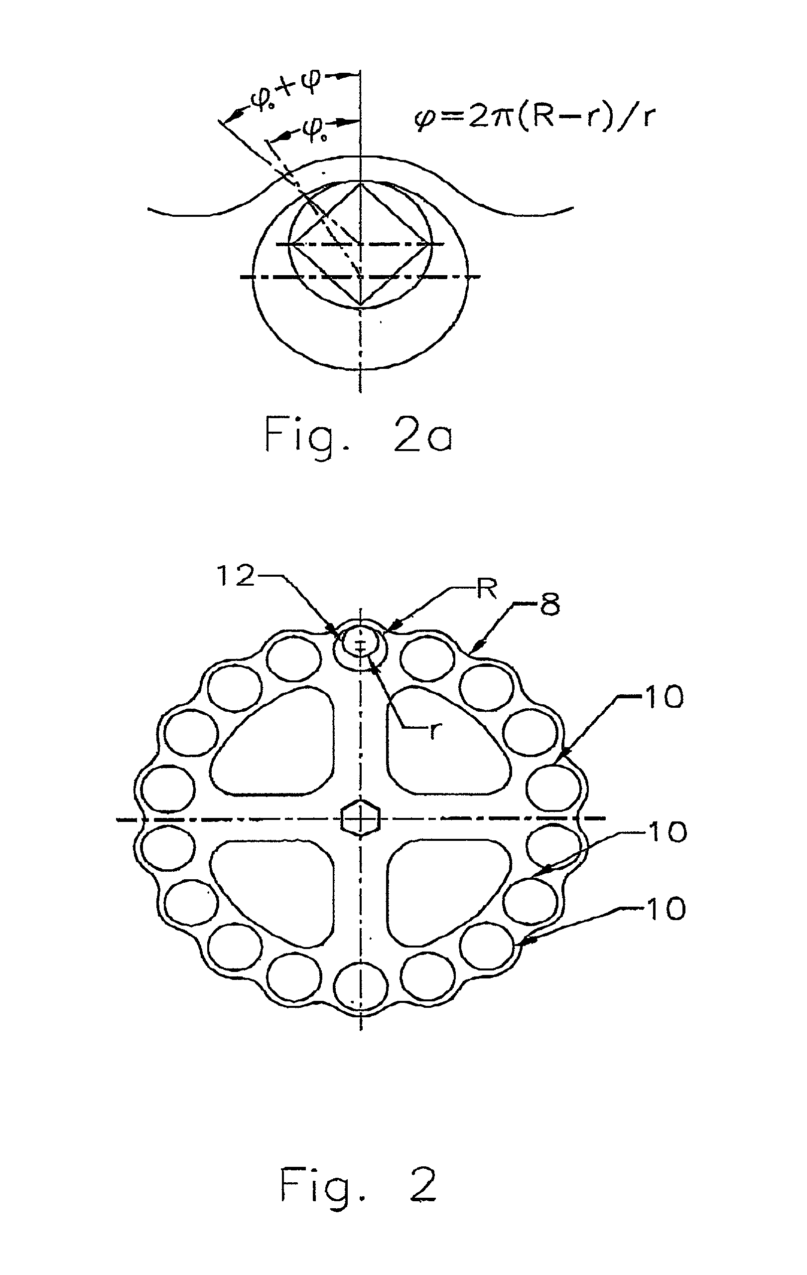
[0060] It will be noted from the embodiments described above that there are no bearings or gears that are utilized to drive the multileveled substrate holders 12 which adds to the simplicity of the design.
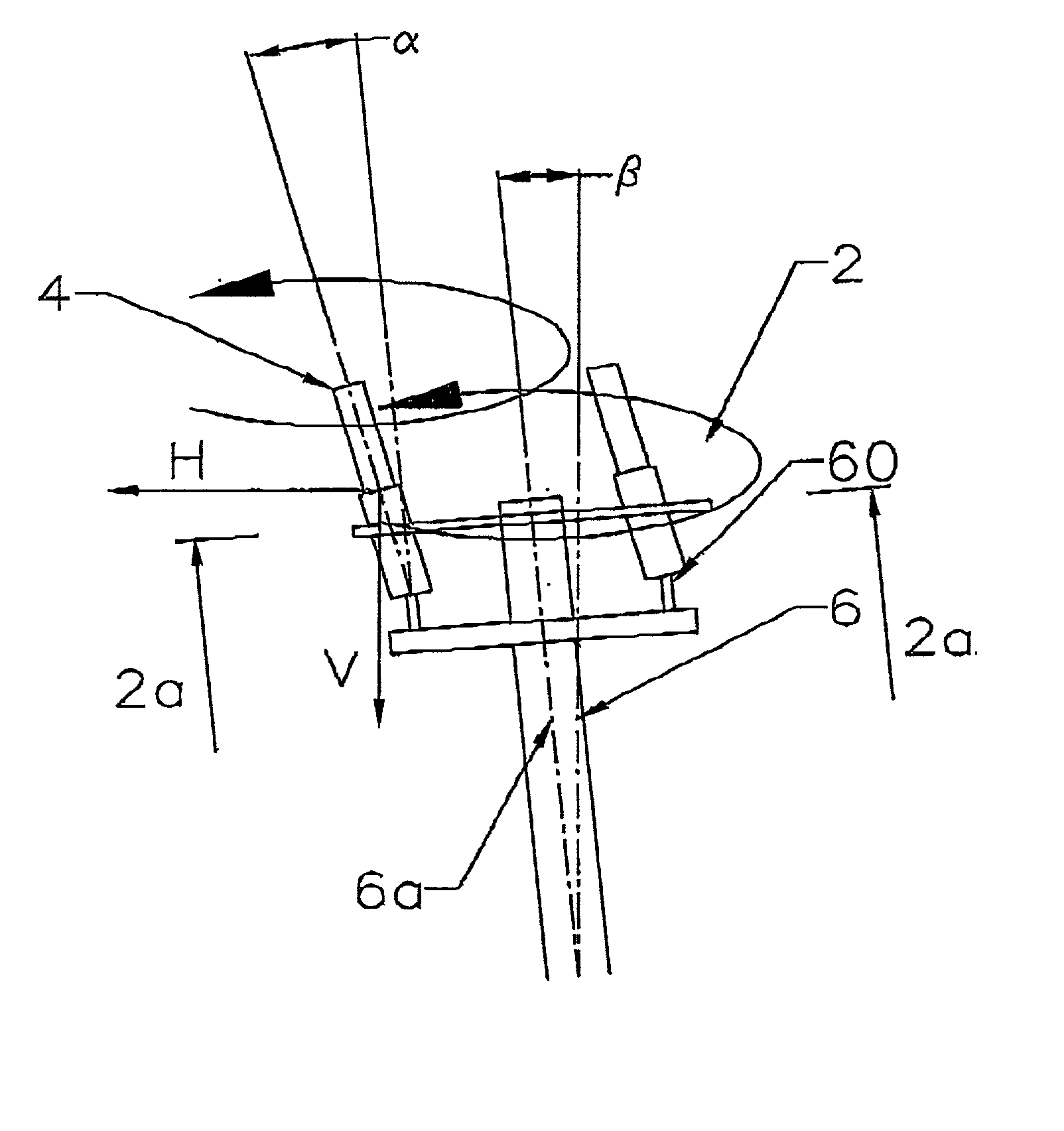
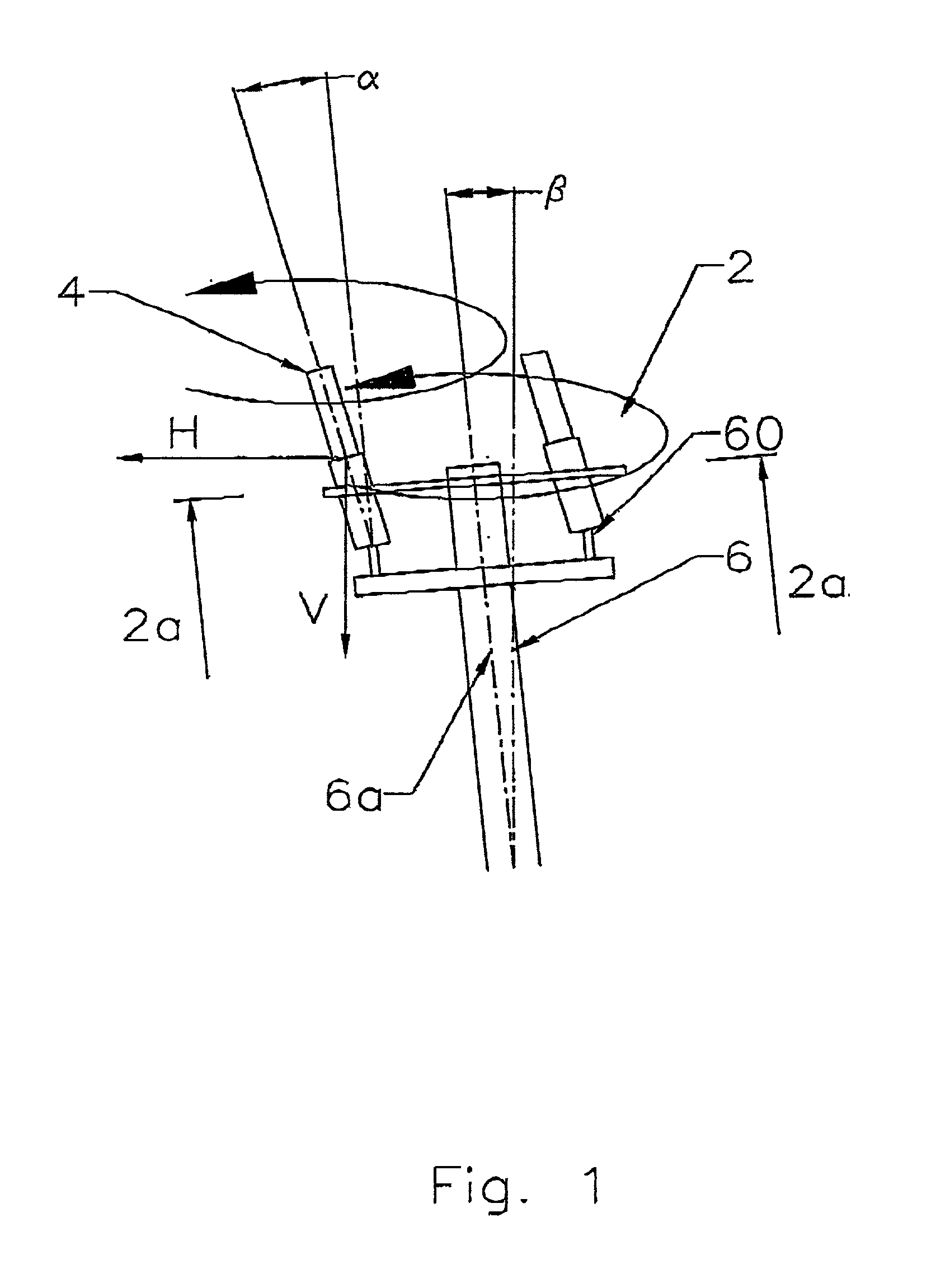
[0061] Furthermore depending on the configuration, weight and size of the material or substrate 4 to be coated various optimal and acute angles will be utilized to produce efficient rotation and exposure to plasma of the substrates during coating. It has been found that so long as the angle is acute good coating results have been produced. In other words the acute angle will generally fall within the range of more than 0.degree. and less than 90.degree. . In other embodiments it has been found that an acute angle of 5 to 10 degrees produces good results. Furthermore an acute angle of 7 degrees has been very useful in producing improved coated results.
[0079] FIG. 13(c) illustrates another embodiment of the invention whereby two intersecting support members 33 are utilized so as to increase the density of the tools 4 to be coated.
[0090] It is apparent from FIG. 16 that the table plate 100 also includes a plurality of electrical insulators 124 which can comprise of a variety of materials including ceramic. The function of the electrical insulators 124 is to support the shields 116 and 126 as shown on FIG. 14 with the intent to eliminate bias potential on the shield 116. The shield 116 inhibits the hard coating material from being deposited onto the moving mechanisms located within the rotating table, such as the bearings and the gears. Furthermore the shield 116 acts as a heat shield and plasma shield.
[0095] As illustrated in FIG. 16, cooling means such as water travels up through the hub 134 and flows outwardly through channels 132 in the direction of arrow A and communicates with the bearing means 140 and 142 through means of water passages or channels 132 so as to carry away excess heat back down through the channels 132 and back down through the hub 134 in direction B in a manner to be more fully described herein. Water is generally used as the cooling means flowing through the channels 132 although other suitable fluids may be utilized. Generally speaking the volume and rate of flow of the water cooling means is selected so that the bearings operate at a temperature that eliminates seizing. Goods results have been experienced by regulating the flow of water so as to operate the bearings at a temperature less than 100.degree. C. FIG. 16 furthermore illustrates the tool driving means consisting of the planetary gear 105 Which is operably connected to the bushings 140 and 142 by means of the shafts 136 which is adapted to receive a nut 144 at one end thereof as well as cotter pin 146 so as to prevent the nut from slipping of the drive shaft 136. The drive means also includes the cooling means consisting of the channels 132 as previously described.
[0098] The various embodiments described herein can be utilized to coat substrates 4 by utilzing any variety of substrate holders which are disposed at an acute angle causing rotation of the substrates 4 as the table rotates within the vacuum chamber 20 so as to more uniformly expose the substrates to the coating deposition material. Such structure minimizes the complicated gearing arrangements utilized in prior art tables. Furthermore such prior art structure creates a massive heat sink which makes it difficult to accurately control the surface temperature of the substrates 4 in a uniform fashion as it is being coated.

Problems solved by technology

It is not always possible to uniformly coat the substrate material even if the substrate material is of a uniform configuration.
The problem of uniformly coating the substrate material is further exasperated if the substrate material is irregular in shape as the coating material is not always uniformly distributed along or within the substrate material.
Furthermore a great number of gears or other rotatable means including bearings and bushings are utilized which presents a very complicated, massive piece of apparatus that must be cleaned and maintained.
Such rotating tables also become coated over time with the coating materials.
Furthermore the massive weight of the rotating table must also be heated which adds to energy costs as well as the necessity for more complicated means of maintaining a uniform temperature within the vacuum chamber.
Such gears and bushings tend to seize up if exposed to elevated temperatures.

Method used


Image

  • Table
  • Table
  • Table

Examples


examples

[0104]

1 Stylus Hardnes Source, Critical radius (load) Coating Substrate Fixture load [L] [.mu.m] [GPa]([g]) TiN WC Chessen, 4.1 50 21(50) conventional TiN WC Chessen, 6.2 50 23(50) new Table TiAIN WC Chessen, 10.3 50 28.3(25) conventional TiAIN WC Chessen, 16.3 50 32.75(25) new Table TiAICN WC Manufacturer 3.6 100* 21.5(50) "B" TiAICN WC Chessen, 4.2 50 28.0(25) conventional TiAICN WC Chessen, 9.0 50 34.0(25) New Table *For samples from "B" low load and smell stylus radius is not available because of the high surface roughness of the coating. *All coatings at 2.5 microns thickness

[0105] As can be seen from the chart referred to above improved critical load, microhardness and adhesion characteristics have been observed by utilizing the method described herein.

[0106] Accordingly the invention described herein provides the following benefits:

[0107] 1. Increased capacities are experienced in loading more substrates 4 to be coated because less space is utilized for the table fixture as c...


PUM

PropertyMeasurementUnit
Thicknessaaaaaaaaaa
Radiusaaaaaaaaaa
Radiusaaaaaaaaaa

Abstract

Structure for disposing a material to be treated at an acute angle relative to the axis of rotation so as to permit the substrate to rotate relative to said structure.

Description

[0001] This invention relates generally to vacuum deposition coating and in particular relates to a rotating table for vacuum deposition apparatus and method therefore.[0002] A number of methods have been developed for depositing materials, generally metals, in the form of particles or ions unto a target surface to form an adherent, uniform coating. Such methods include thermo deposition, cathode sputtering and chemical vapour deposition.[0003] These techniques are usually conducted in a vacuum chamber having a cathode source, an anode source, a table or platen for supporting the substrate to be coated.[0004] Generally speaking it is desirable to uniformly coat substrate material.[0005] It is not always possible to uniformly coat the substrate material even if the substrate material is of a uniform configuration. The problem of uniformly coating the substrate material is further exasperated if the substrate material is irregular in shape as the coating material is not always uniform...

Claims


Application Information

Patent Timeline
IPC IPC(8): C23C14/50
CPCC23C14/505
Inventor GINOVKER, ANDREYDRUKER, LEONIDMOLENDA, DAREKWARZYSZYNSKI, MARIUSZ
Owner GINOVKER ANDREY
Learn More