
Corrugated cardboard plates, method of and apparatus for making the same

a cardboard plate and corrugated technology, applied in the field of corrugated cardboard plates, can solve the problems of large cutting force, unsatisfactory retention of adhesive on the cut face of honeycomb units, and the complexity of the apparatus for making the honeycomb structur

Inactive Publication Date: 2002-05-30
TAIZEN CO LTD
View PDF0 Cites 27 Cited by
  • Summary
  • Abstract
  • Description
  • Claims
  • Application Information

AI Technical Summary

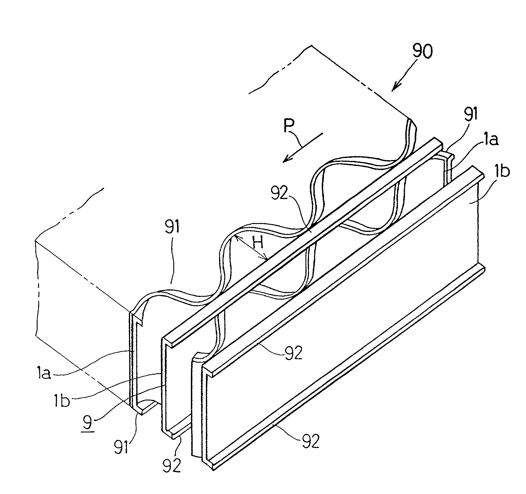
Benefits of technology

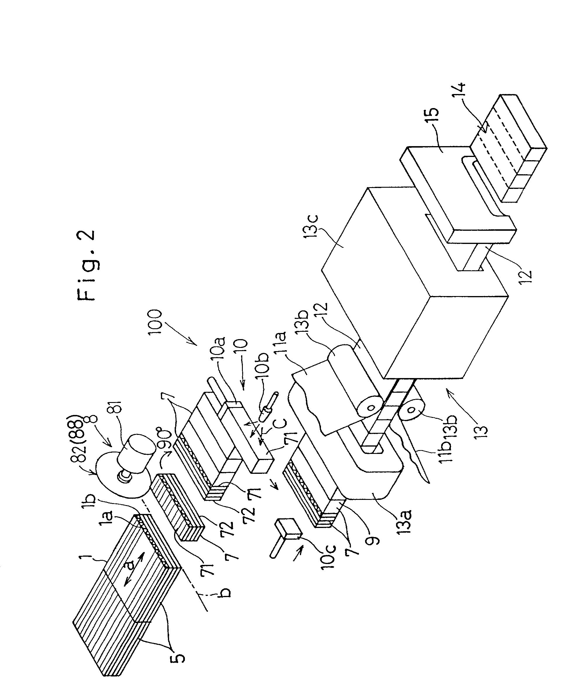
[0009] With the above described corrugated cardboard plate making method, when the corrugated cardboard laminate is to be cut along cutting lines lying perpendicular to ridge lines of the corrugated sheet into a plurality of corrugated blocks, not a guillotine cutter including a single knife blade, but a circular saw or a band saw including a body having its tip formed with rows of equally spaced saw teeth or a so-called raking saw having a plurality of equally spaced saw teeth that are alternately offset laterally relative to each other to provide two rows of alternating saw teeth, can advantageously be employed. In other words, since the corrugated cardboard laminate is of a design wherein corrugated cardboards are laminated together with the cells left open and does not require a relatively large force during the cutting thereof, the use of the circular saw, the band saw or the ranking saw is possible. For this reason, cut faces of each of the corrugated cardboard blocks resulting from cutting of the corrugated cardboard laminate can be suitably roughened and, therefore, by applying an adhesive to the cut faces of each of the corrugated cardboard blocks optimally, the sheet can be assuredly and firmly bonded. Accordingly, no surface roughening need not be performed with the use of the surface roughening device and the expander such as required in the previously suggested apparatus. Accordingly, it is possible to continuously manufacture at a reduced cost the corrugated cardboard plates having excellent heat and sound insulations and being lightweight and robust and, yet, capable of exhibiting a performance comparable to or higher than that exhibited by the use of the honeycomb core material.
[0011] The corrugated cardboard plate making method of the present invention can easily be practiced by the use of the corrugated cardboard plate making apparatus of the structure described above.
[0012] In a preferred embodiment of the present invention, during the formation of the corrugated blocks or in the corrugated block former performing the formation of the corrugated blocks, bent portions are formed at opposite ends of the corrugated sheet, that are positioned on front and rear sides thereof, so as to extend in a direction parallel to the front and rear sides by means of cutting performed by a cutter. The presence of these bent portions is effective to increase the physical strength of the corrugated sheet. Moreover, when the sheet is bonded to one or both of front and rear sides, the bonding surface area can increase because of the presence of the bent portions and, therefore, the bonding strength of the sheet can be increased.
[0014] The corrugated cardboard plate of the present invention is excellent in heat insulation and sound insulation and, also, lightweight and has a strength and, therefore, can be used as a floor panel, a partition wall, an external wall, a load bearing pallet, a core material for a table, a counter or a shelf, a core material for audio appliances or office automation appliances, a cushioning material for packages, a corner member for packaging, or a filter when filled with a mass of titanium oxide or activated carbon particles, or an element for a heat exchanger. Thus, the corrugated cardboard plate of the present invention can find a variety of applications.
[0016] In another preferred embodiment of the present invention, each of the bent portions has a length within the range of 1.0 to 5.0 times the thickness of the corrugated sheet. By so doing, the physical strength of the corrugated cardboard plate can be increased and bonding of the sheet to the bent portions can be assuredly achieved. At this time, if the length of each of the bent portions is chosen to be of a value smaller than 1.0 times the thickness of the corrugated sheet, no sufficient physical strength can be obtained and no sufficient bonding of the sheet can also be obtained. On the other hand, if the length of each bent portion is chosen to be of a value greater than 5.0 times the thickness of the corrugated sheet, no simplified and efficient formation of the bent portions is possible. In other words, the corrugated cardboard plate is prepared by cutting corrugated cardboard laminates into a plurality of corrugated cardboard blocks by the use of a saw, which blocks are in turn connected together with upper and lower faces thereof bonded with each other. Therefore, if the bent portions are formed by the utilization of margins left at the cut ends of each of the corrugated cardboard block at the time of cutting by means of the saw, no separate manufacturing step is required and the bent portions can advantageously be formed simultaneously with the cutting. However, if the length of each of the bent portions exceeds a value greater than 5.0 times the thickness of the corrugated sheet, simultaneous formation of the bent portions with the cutting saw will become difficult. Accordingly, in order for the bent portions to be formed efficiently by the utilization of the manufacturing step of the corrugated cardboard plates, the length of each of the bent portion should be within the specific range as described above. Also, since the corrugated cardboard plate of the structure described above is excellent particularly in physical strength, it can be optimally utilized when used as material for the load bearing pallet, the furniture or the core material for the rack.

Problems solved by technology

However, the apparatus for making the honeycomb structure tends to become somewhat complicated.
However, at the time the honeycomb units are formed by cutting the honeycomb core material, a relatively large cutting force is required since the cutting is performed while the honeycomb cells are closed.
However, the use of the guillotine cutter results in a smooth cut face (a face where an adhesive is to be applied) and, therefore, the adhesive applied will not be satisfactorily retained on the cut faces of the honeycomb units, with the consequence that the sheet will not be firmly bonded to the elongated honeycomb core.
At this time, if the length of each of the bent portions is chosen to be of a value smaller than 1.0 times the thickness of the corrugated sheet, no sufficient physical strength can be obtained and no sufficient bonding of the sheet can also be obtained.
On the other hand, if the length of each bent portion is chosen to be of a value greater than 5.0 times the thickness of the corrugated sheet, no simplified and efficient formation of the bent portions is possible.
However, if the length of each of the bent portions exceeds a value greater than 5.0 times the thickness of the corrugated sheet, simultaneous formation of the bent portions with the cutting saw will become difficult.
In other words, since the height of the cells in the standard corrugated cardboard is generally within the range of 1.1 to 4.8 mm, a relatively large number of the standard corrugated cardboards is required to produce the corrugated cardboard plate of a predetermined size and results in increase of the weight of the resultant corrugated cardboard plate.
Also, from the standpoint of saving of the limited resources, it is problematic.
On the other hand, if the height of the cells in the corrugated cardboard is greater than 15 mm, it may result in reduction of the weight, but the strength will be insufficient.

Method used


Image

  • Corrugated cardboard plates, method of and apparatus for making the same
  • Corrugated cardboard plates, method of and apparatus for making the same
  • Corrugated cardboard plates, method of and apparatus for making the same

Examples


Embodiment Construction

[0035] Preferred embodiments of the present invention will now be described with reference to the accompanying drawings.

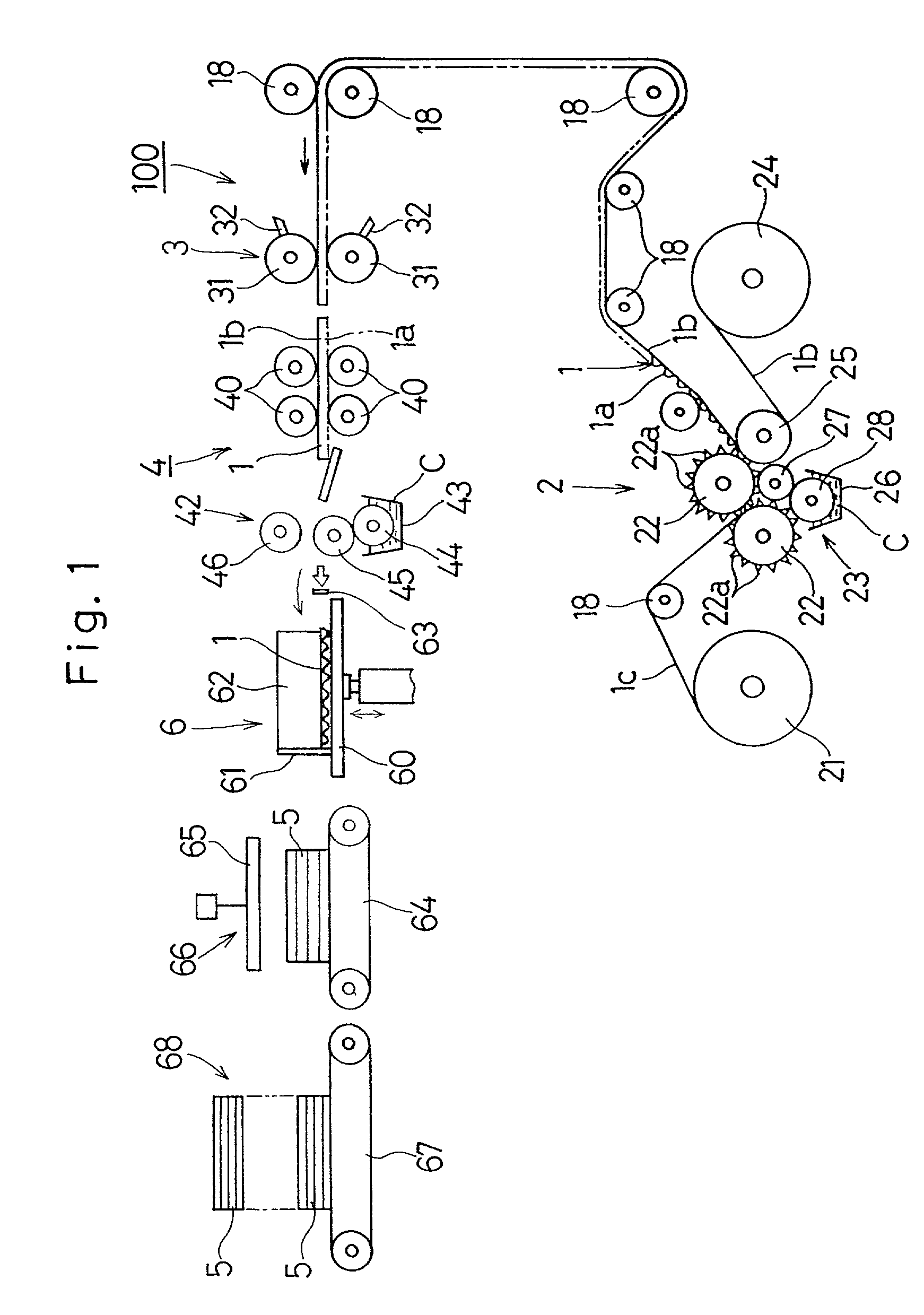
[0036] Referring first to FIGS. 1 and 2, there is shown an apparatus 100 for manufacturing flat corrugated cardboard plates each made up of a plurality of corrugated cardboards laminated together. It is to be noted that for the convenience of drawing, the cardboard plate manufacturing apparatus 100 is divided into two units which are shown in FIGS. 1 and 2, respectively. As shown in FIG. 1, the cardboard plate manufacturing apparatus 100 includes a corrugated fiberboard former 2 for making a continuous strip of corrugated fiberboard 1A made up of a corrugated sheet 1a and a liner sheet 1b bonded to the corrugated sheet 1a, a cutting machine 3 including a pair of juxtaposed rotary drums 31 and 31 and cutter blades 32 and 32 mounted on the respective rotary drums 31 and 31 for cutting the continuous strip of corrugated fiberboard 1A into a plurality of corrugated car...


PUM

PropertyMeasurementUnit
Heightaaaaaaaaaa
Thicknessaaaaaaaaaa
Lengthaaaaaaaaaa

Abstract

Corrugated cardboard plates are made by laminating and bonding corrugated cardboards 1, each including a corrugated sheet 1a and at least one liner sheet 1b bonded to the corrugated sheet 1a, to provide a corrugated cardboard laminate 5, which is in turn cut along a plurality of cutting lines b lying perpendicular to a direction parallel to ridge lines a of the corrugated sheet 1a to provide a plurality of corrugated blocks 7. The corrugated blocks 7 are then arrayed in a line to provide an elongated flat corrugated plank 9 in which the top face of one of the corrugated blocks 7 is bonded to the bottom face of the next adjoining corrugated block 7. At least one backing sheet 11a or 11b, made of paper, to one of opposite surfaces of the elongated flat corrugated plank 9 and is subsequently cut into a plurality of corrugated cardboard plates 14 of a predetermined size. In this way, the corrugated cardboard plates 14 or 90 can be obtained at a reduced cost, each of the plates 14 or 90 having an excellent heat insulation, a sound insulation and being lightweight and robust.

Description

[0001] 1. Field of the Invention[0002] The present invention relates to corrugated cardboard plates, a method of and an apparatus for making the corrugated cardboard plates from corrugated cardboards that are excellent in heat insulation and sound insulation, and have a lightweight feature and a strength. The present invention also relates to the corrugated cardboard plates and architectural elements utilizing the corrugated cardboard plates.[0003] 2. Description of the Prior Art[0004] The assignee of the present invention has applied for patent on an apparatus for and a method of continuously manufacturing a honeycomb structure that can be used as a material for furniture and architectures (the Japanese Laid-open Patent Publication No. 11-235773). This honeycomb structure is lightweight and has cells exhibiting an extremely high compressive strength and is excellent in heat insulation and sound insulation. However, the apparatus for making the honeycomb structure tends to become so...

Claims


Application Information

Patent Timeline
IPC IPC(8): B32B3/28E04C2/36
CPCB31D3/007B31F1/2813B32B3/28E04C2/36Y10T156/1343Y10T428/24694Y10T156/1072Y10T156/12Y10T156/1069Y10T428/24711Y10T156/1052Y10T156/1016Y10T156/13B32B29/08B32B2307/304B32B2250/26B32B29/005B32B2307/102
Inventor YOSHII, HISASHI
Owner TAIZEN CO LTD
Learn More